Now that I’ve escaped from Berkeley, I have free time again. Evenings, weekends–they exist. Almost organically, my desire to do things has been recovering. So I hatched a new project: a MAME box. MAME stands for ‘multiple arcade machine emulator,’ and it’s a project to resurrect classic (and modern) arcade games by meticulously emulating the original hardware that they ran on. It can run everything from Galaga to Street Fighter. At first, I planned to do the whole shebang: a full-size arcade cabinet with a classic arcade monitor. I was inspired by Doug’s MAME cabinet that he built in college.
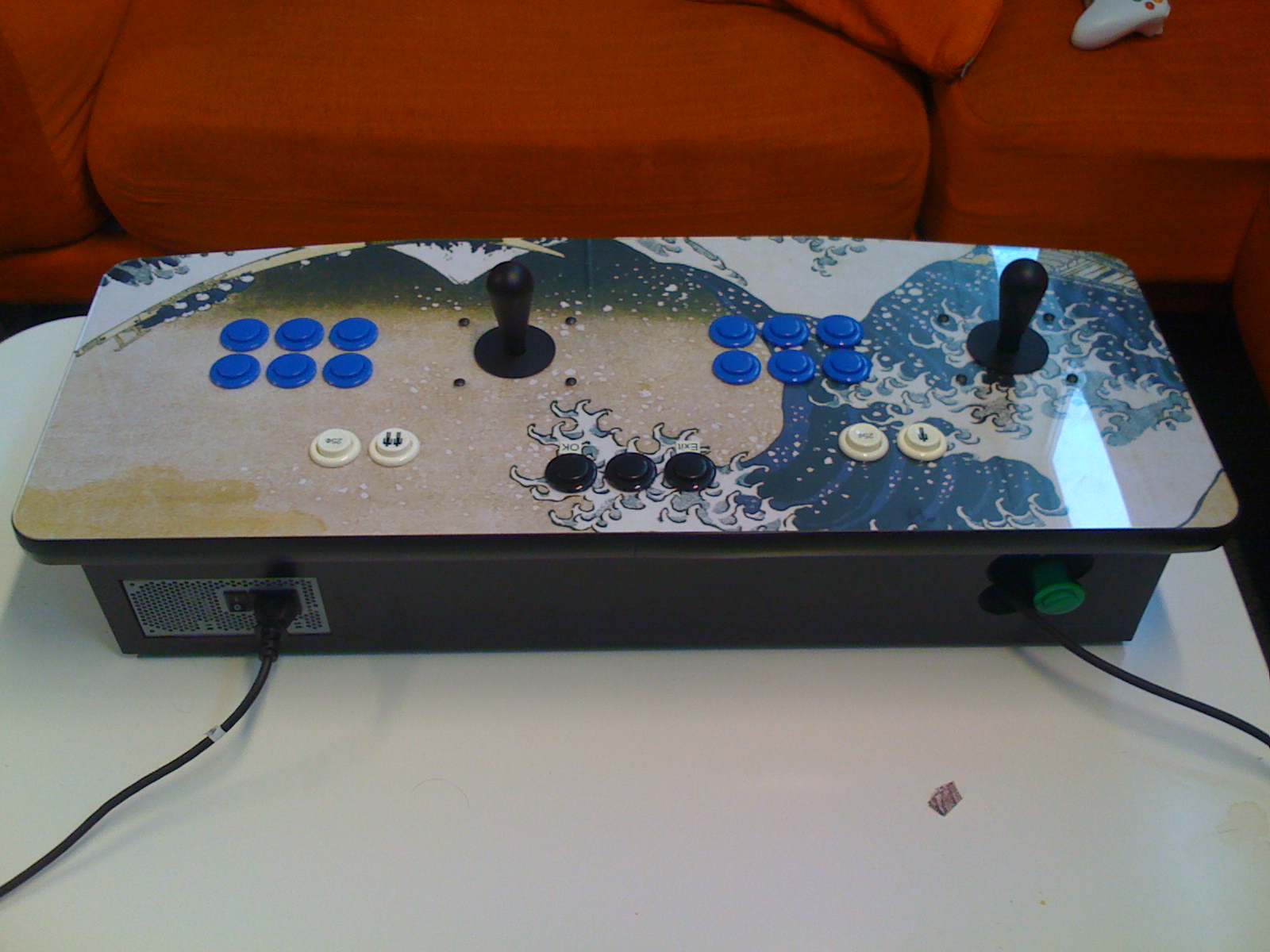
I couldn’t get over one serious drawback of the full cabinet: it is immobile. Done properly, it’s about 6 and a half feet tall and weighs a couple of hundred pounds. So wherever I built it would be where it stayed. Instead, I decided to build just the control panel of the cabinet, with a computer running MAME inside the control panel enclosure. The finished product would fit easily in a car, and connect via HDMI to existing A/V setups. I batted the idea around until Doug and George surprised me with a set of computer-cut wood pieces to make the box out of. From there, it all came together pretty rapidly. The finished product:
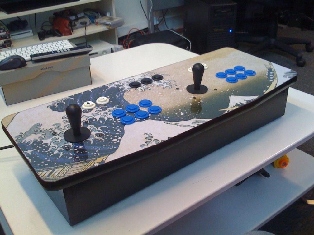
I decided to call it “The Great Wave” because I used Hokusai’s famous woodcut The Great Wave off Kanagawa as the artwork for the top surface. Here’s a description of how we (Doug, George and I) built it over about six weekends at the beginning of the year.
First, the box design and woodworking. Doug and George went to an arcade to measure the control panels of a stock Street Fighter cabinet, just to make sure the spacing of the buttons and the joysticks was legit. He transferred the measurements into a Corel Draw design for the top of the board. Here’s what it looks like:

Each player gets six buttons, which is enough for pretty much any game from an arcade or classic console. The two buttons above each player’s layout are for player one/player two start and coin insert. The three at the top are dedicated to navigating through the emulator menus.
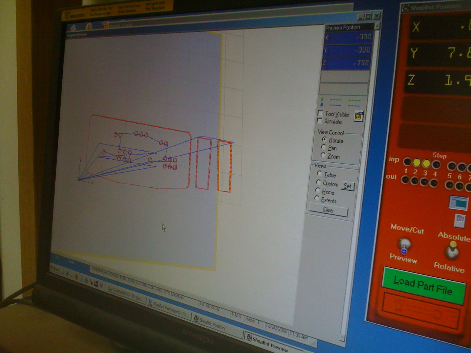
The other five sides of the box were considerably simpler, but Doug did put a nice subtle tilt in from back to front for comfort. Designs in hand, Doug and George headed to the Sawdust Shop, a treasure trove of woodworking equipment that you can rent time in by the hour, to actually do the cutting. The precision cutting on the top was done by a computer-controlled CNC router. The material was medium-density fiberboard (MDF for short), a particle board with good strength that is cheap and easy to work with. Here’s the design loaded into the CNC computer software:
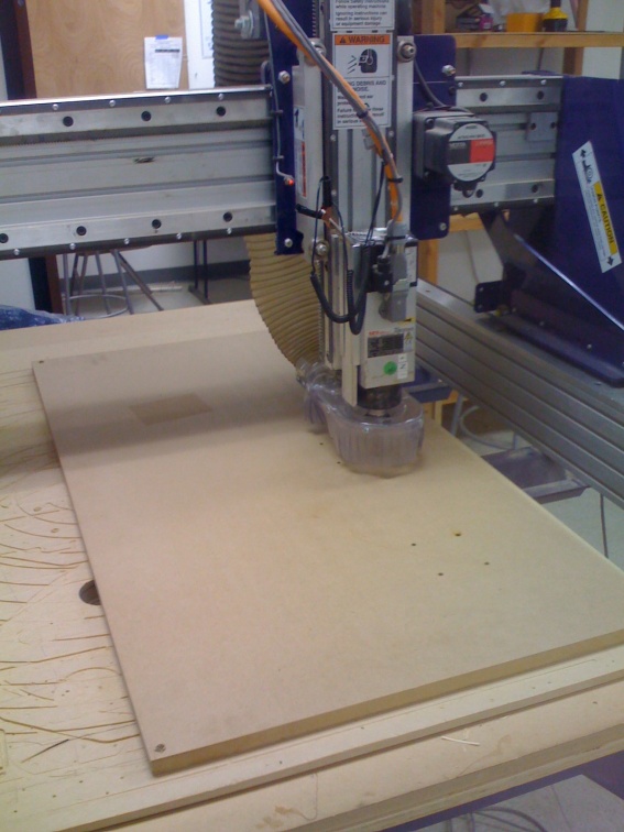
Here’s a shot of the machine starting to do the cutting:
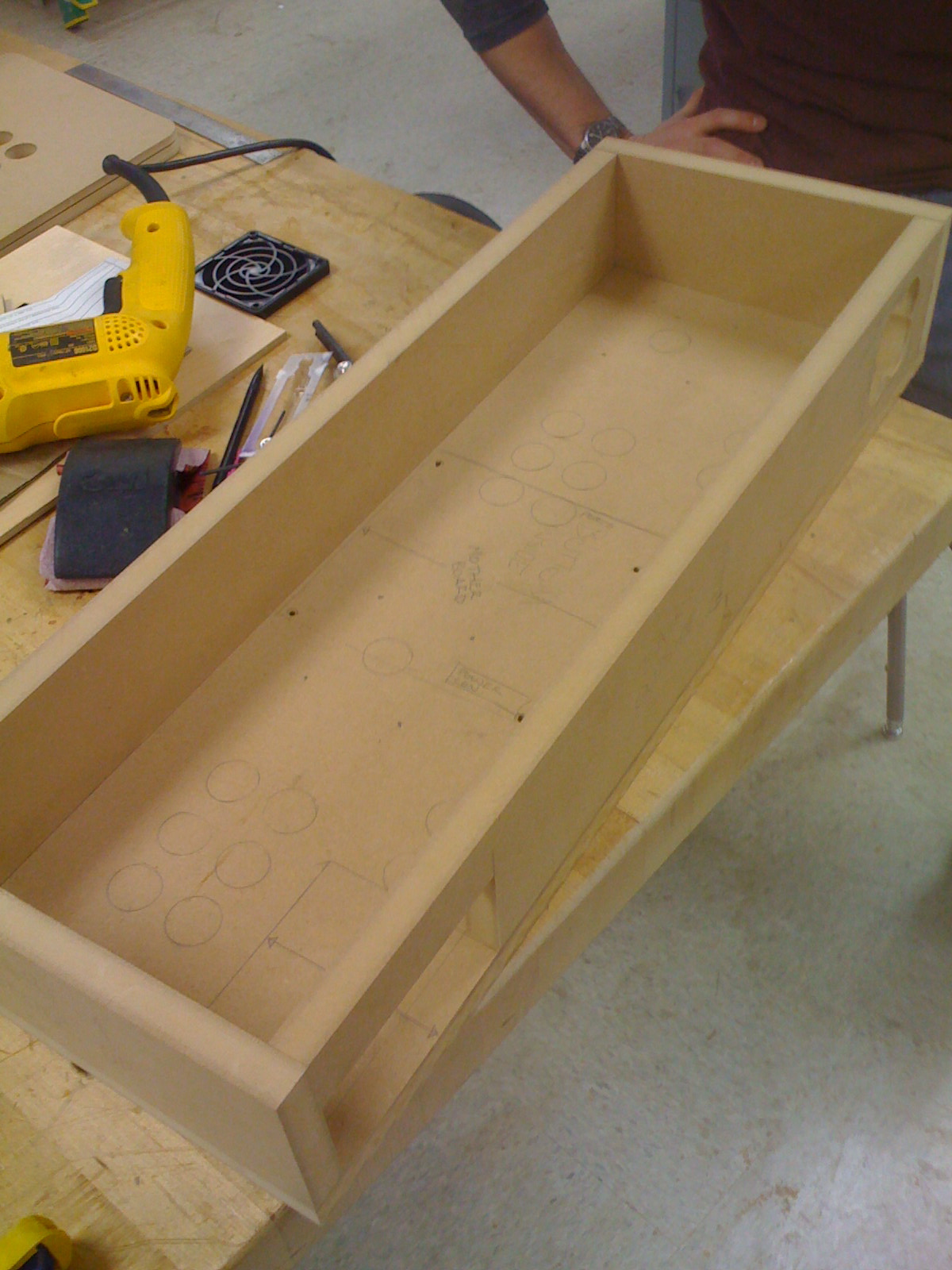
After all the pieces were cut, Doug and George presented me with them. The intent was to then hassle me until I got off my ass and finished the rest of the project. Hardly any hassling was necessary, it turned out.
Along with the MDF cutout of the control panel, they had a piece of plexiglass (acrylic) cut to lay on top for a nice, plastic finish. Trouble was, the acrylic chipped when the CNC router bit (made for wood) tried to cut it, leaving a rough edge all around. You can buy router bits made to cut acrylic, but for the price of the bit alone (about $40), I had a new acrylic overlay custom laser-cut by Pololu custom laser cutting. These guys were great. Even with the time to look over the design and give me a quote, I had the finished piece in my hands within a week.
With all the pieces of the box in hand, it was time to think about the controls. I bought my pushbuttons and joysticks directly from Suzo-Happ, manufacturers of American-style arcade equipment. These are the controls you remember from your youth, if you ever visited arcades in the US–big, beefy joysticks capped with bat-shapped plastic handles a clicky, indestructible-feeling buttons.
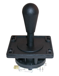

Despite some quite lengthy arguments that Japanese-style arcade controls are superior to American parts, I find that the Japanese parts feel flimsy and don’t offer the same satisfying feedback. Also, I intended the control panel to withstand pounding on from drunk and/or infuriated players, so the delicate precision of the Japanese controls seemed like a bad way to go.
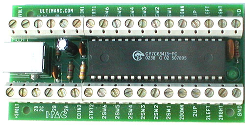
The buttons themselves use small microswitches (the white things with the prongs attached to the bottom) to close an electric circuit when you press them. To use them to control the MAME software, you have to translate the opening and closing of the circuit into a keyboard button press. Building MAME cabinets is common enough that a company, Ultimarc, has sprung up specifically to provide circuit boards that translate arcade control signals into keyboard button presses. In particular, I used their IPAC VE board to connect all my controls via USB to the computer running MAME.
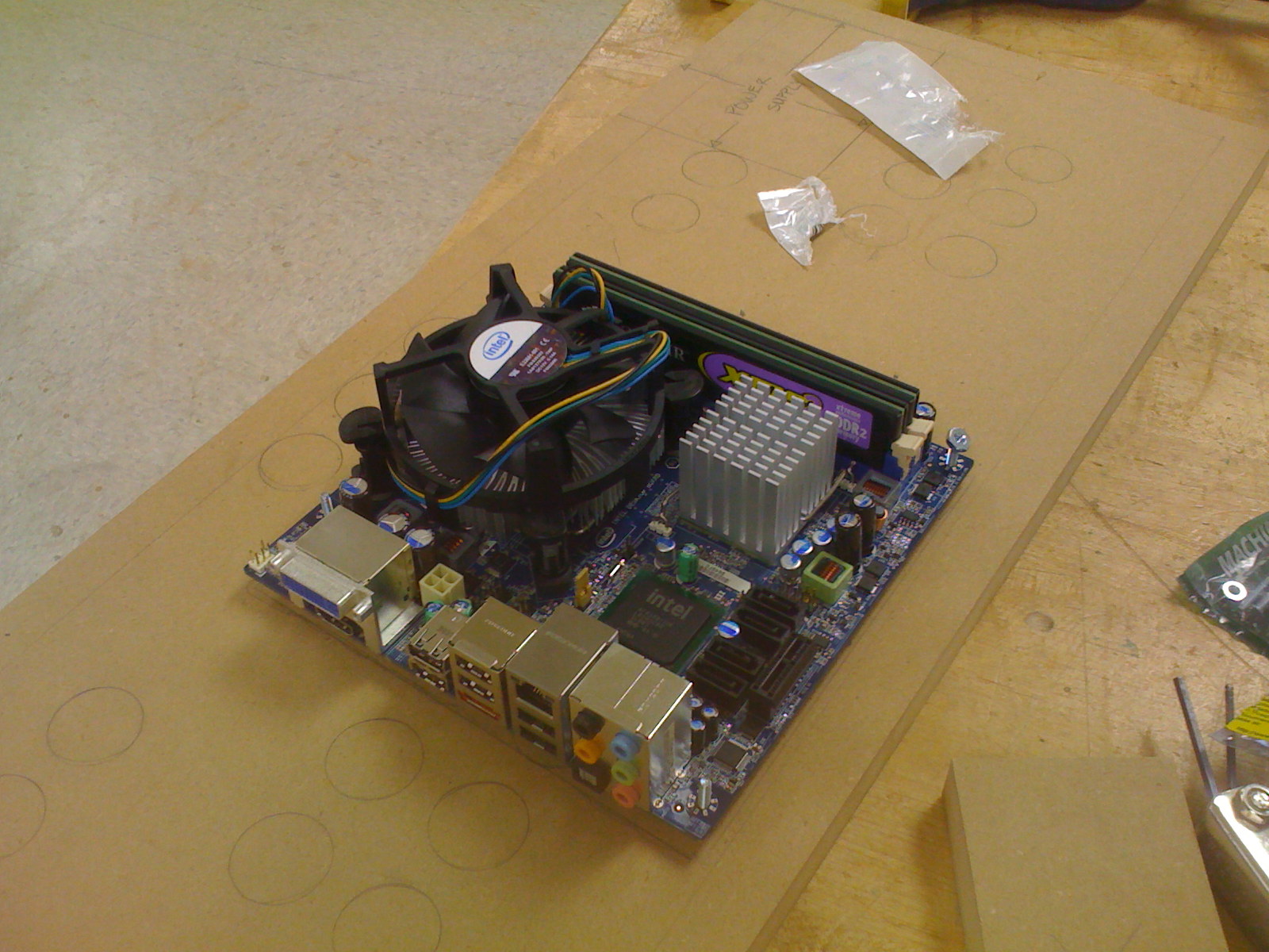
The last big piece to consider was the computer that would fit inside the box and run MAME. I didn’t have a lot of space to work with, so I was restricted to looking for very small-form-factor boards. I ended up going with Intel’s DG45FC, a mini-ITX board about 8 inches to a side that had integrated video with HDMI out. To keep power consumption low and noise down (and to save money), I paired it with a low-end but still speedy 45nm Pentium 5200 dual-core chip. I got an ITX power supply to mount elsewhere in the box (more on that later).
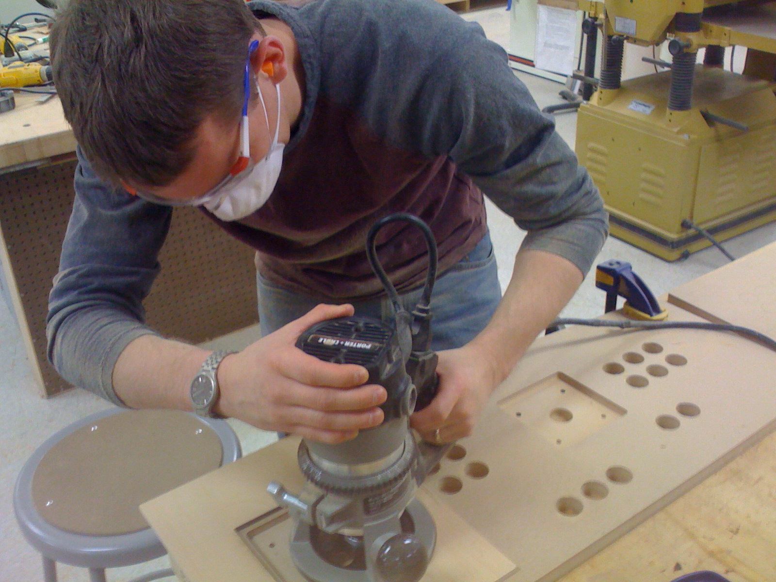
With the parts decided, Doug and I headed back to the wood shop for another day of construction. The control panel is cut out of 3/4″ MDF, which is pretty thick, and I thought it made the joysticks sit too low. So, we started out by routing out half the thickness of the board around the joystick mounts. It was my first experience using a router, which seems to be the solution to pretty much every wood working problem. Not pictured is the trickiest routing task we faced that day: cutting a 1/16″ slot all around the edge of the control panel to install T-molding for a nice finish to the edge. Doug had to handle that one.
Next, we drilled holes in the bottom of the box to mount the motherboard. Here’s a test of the fit–the fan gives away how tiny the board is:
After cutting holes in the rear panel for the power supply and cords, we loosely assembled the box to prepare to glue it all together.
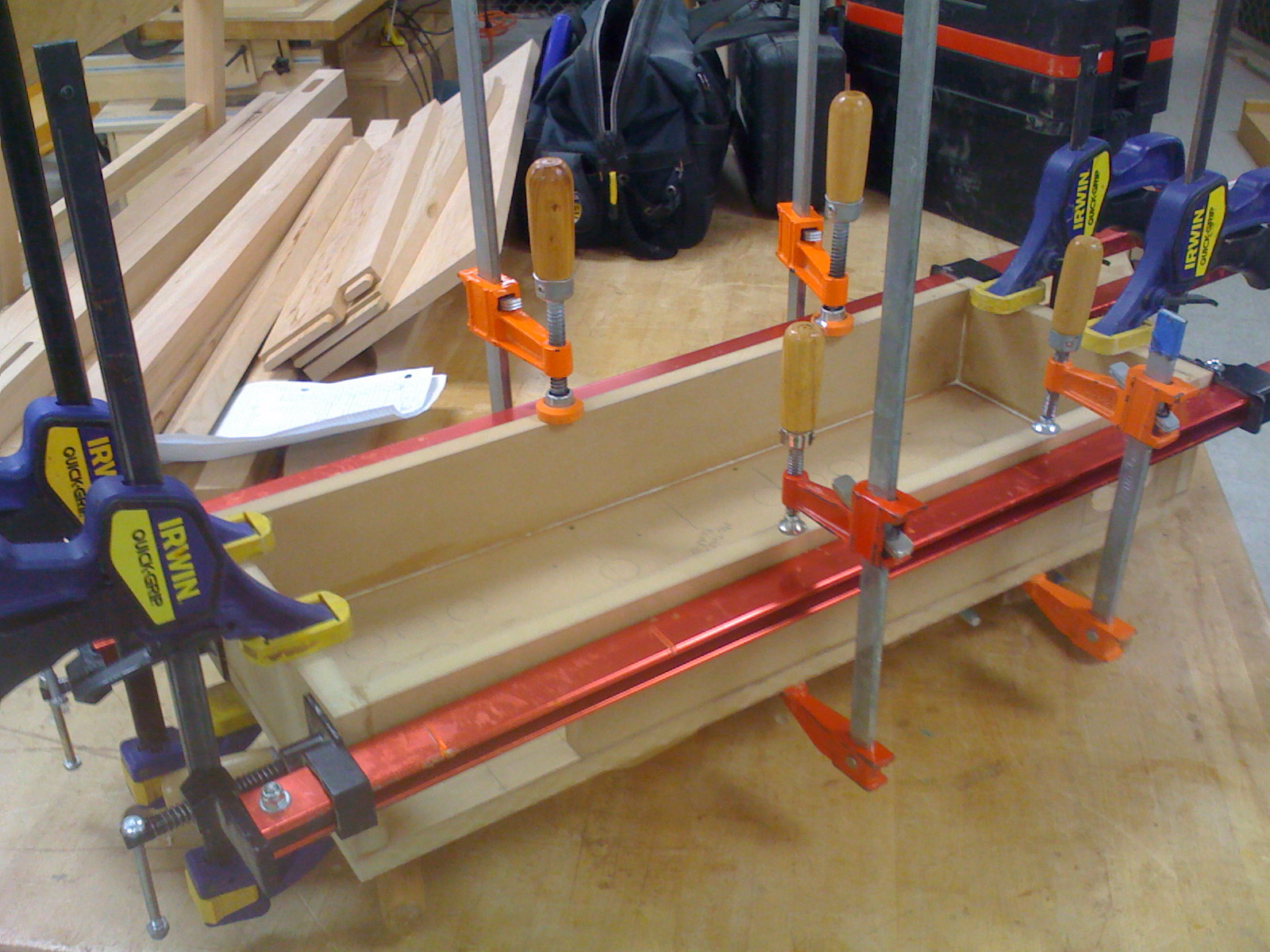
We covered all the mating pieces with standard wood glue, squared them up and clamped them. One of the nice things about renting time in a big wood shop is access to an unlimited supply of clamps. We may have taken things too far.
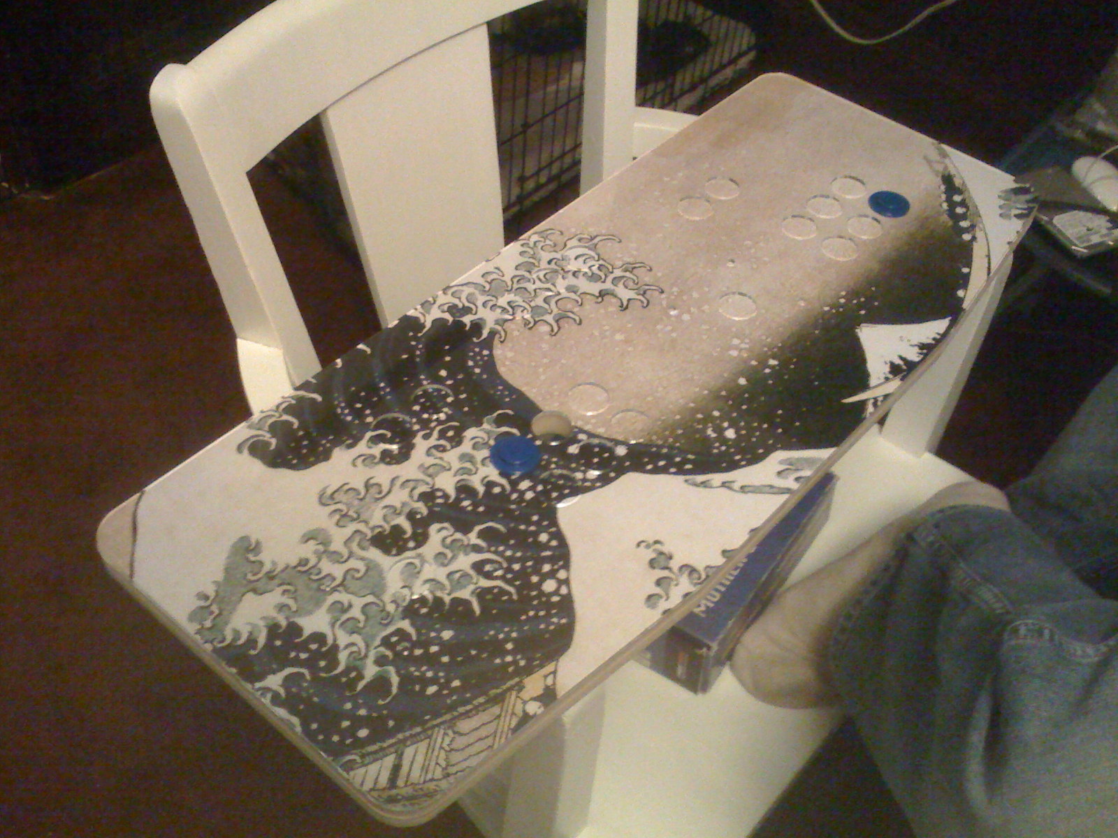
We let the box set up while we got dinner, then picked it up and drove back to Oakland. We got in at 9pm, but we had too much momentum not to start working on the electronics of the control panel immediately. We sandwiched a print of The Great Wave between the MDF and the laser-cut acrylic. We tacked it in place with two buttons, then trimmed away the excess from around the edge and each button hole.
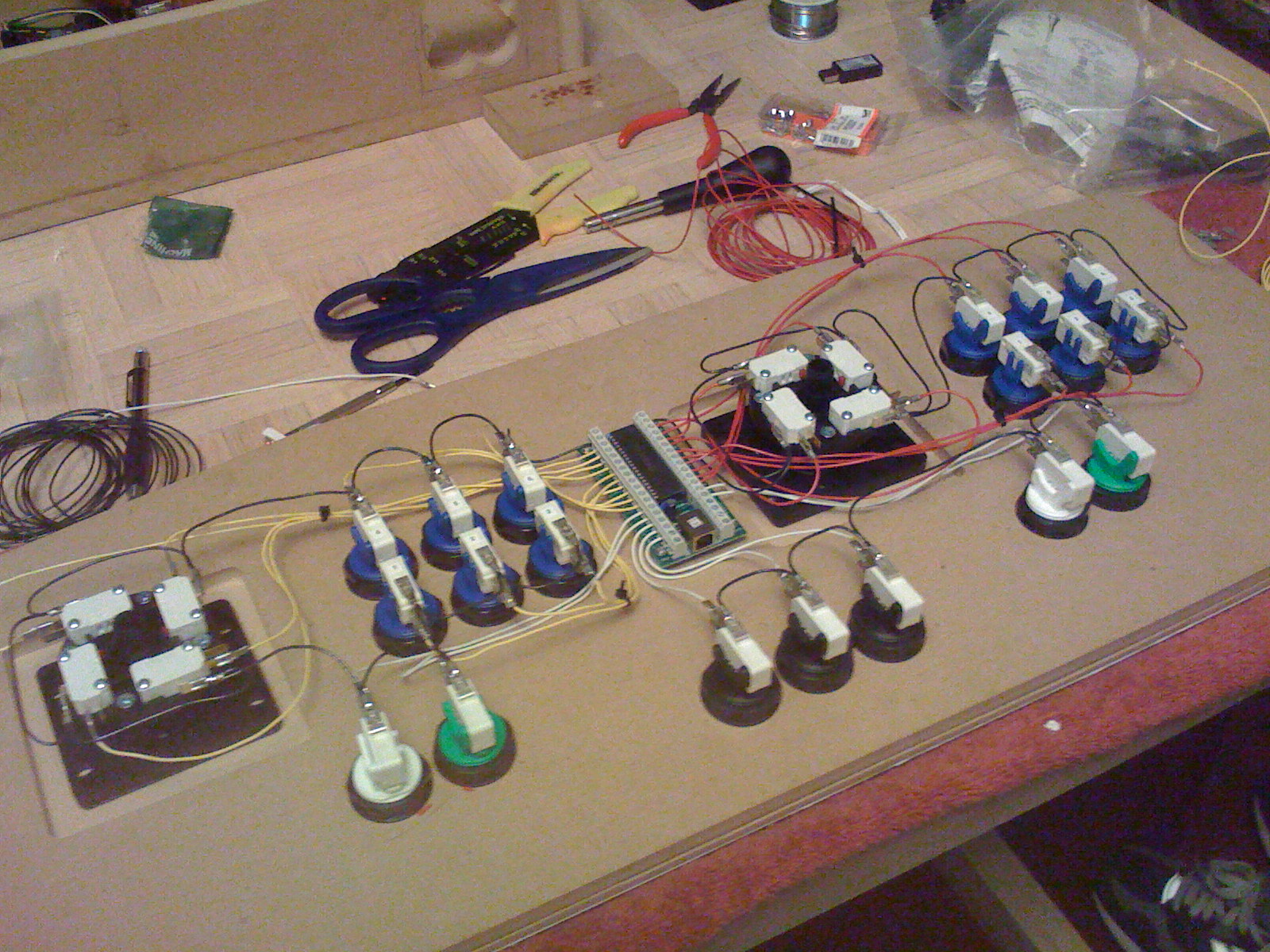
Next, we bolted on the rest of the buttons and the joysticks and drilled holes to mount the keyboard encoder.
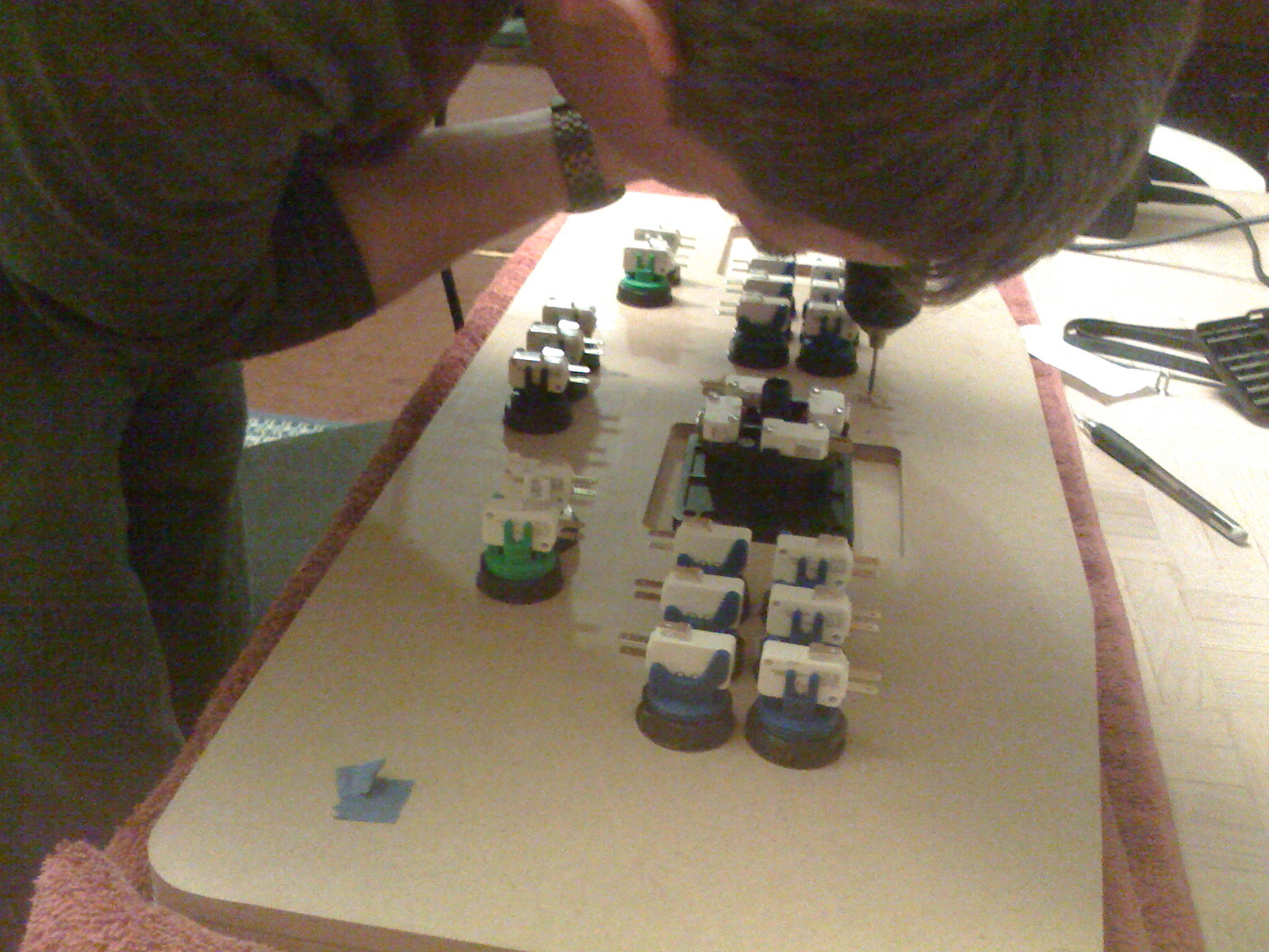
Fueled by mexican beer, we dove into stripping, crimping and soldering the signal wires for all the controls. Doug brought his Metcal soldering iron, which made the whole thing a breeze.
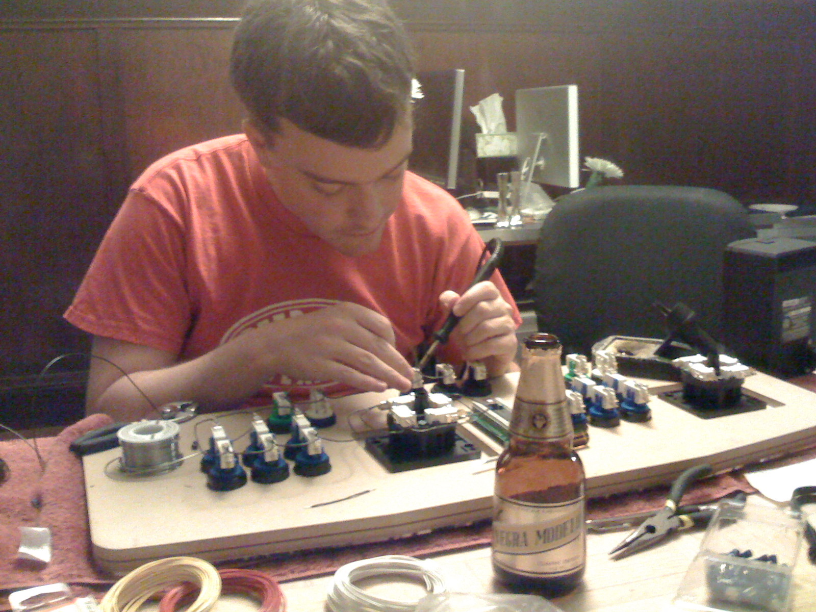
By the time we went to bed, all the wiring was complete.
Over the next week as the last parts arrived, I painted the box, installed the hinge to hold the control panel on, and added the T-molding around the edge. Here’s a picture of the interior of the final, assembled box:
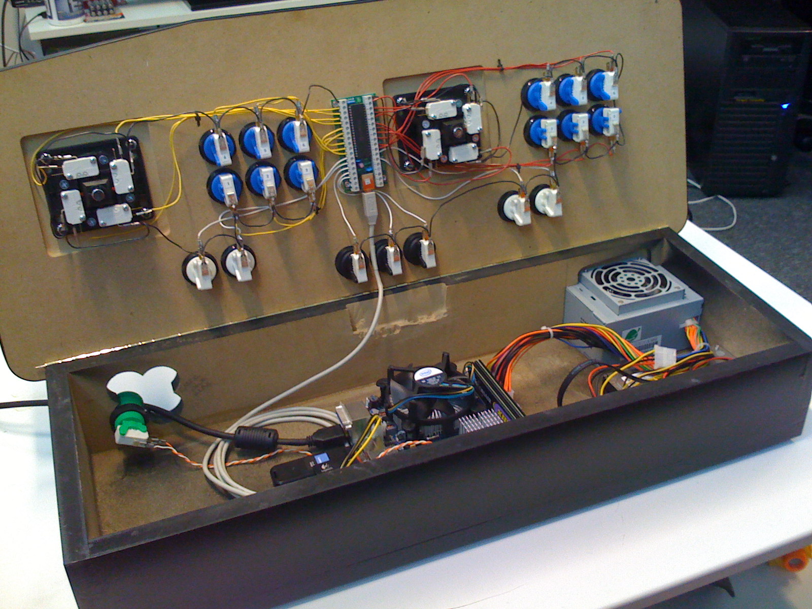
The one cable you see leaving on the left is the HDMI cord that carries audio and video to the TV. I rigged up an extra green button for the power switch of the computer. Here’s one more shot of the box, from the back. You can see the cutout for the power supply, which also provides hot air exhaust for the enclosure.