Lest you think overt.org, which is 25 years old, was my first foray into personal web publishing, behold Bryanthia, the first web page I can recall creating at age 15 in 1996. I was inspired to dig this up by tom7’s recent project where he touts his webpage from 1996 to go digging in my old personal backups for my first site. Turns out it’s from the same year, and it includes some sweet scanned climbing photos and a 3D rainbow Phish logo. Enjoy this 30-year-old website, best viewed in Netscape or Internet Explorer 4 or later!
The toilet in our upstairs bathroom had a weak flush, probably for at least a couple of years. I hate it when shit doesn’t work and I’m not afraid to fiddle with toilets, so I had tried everything in my repertoire: adding and removing water from the tank level, the bowl level; snaking out the drain, plunging the hell out of it. Nothing helped. I felt lost and with a vague dread that the poorly flushing toilet was indicative of bad drainage in our main sewer, and that nothing was going to fix that, and the bad flush was just going to remind me about it constantly for years.
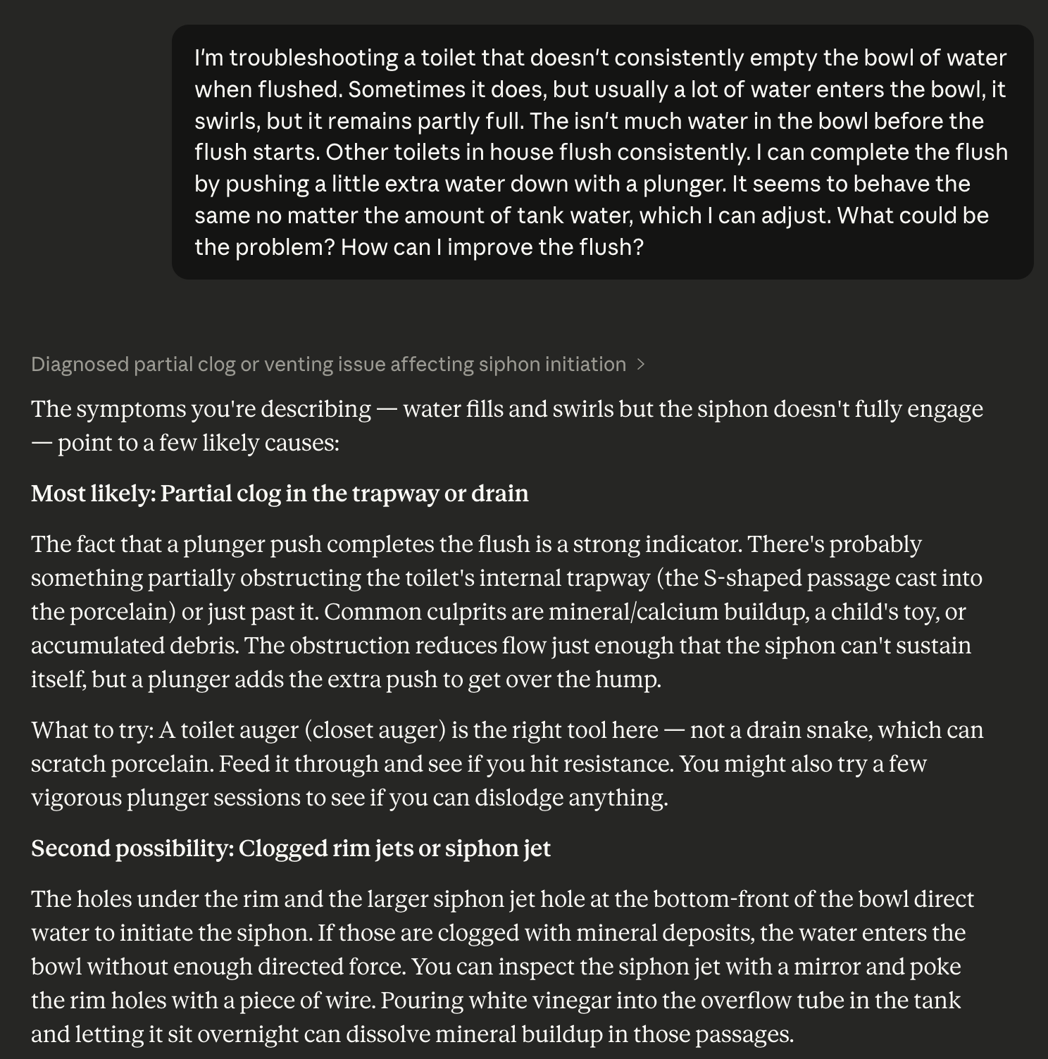
I don’t know why it took so long for me to think of asking Claude about it. When I did, things immediately started to feel more manageable:
Alright, now we’re talking! But I already tried clearing clogs. But Claude presented me with another option here: “clogged rim jets or siphon jet.” What the hell is a siphon jet?! But then it got even better:
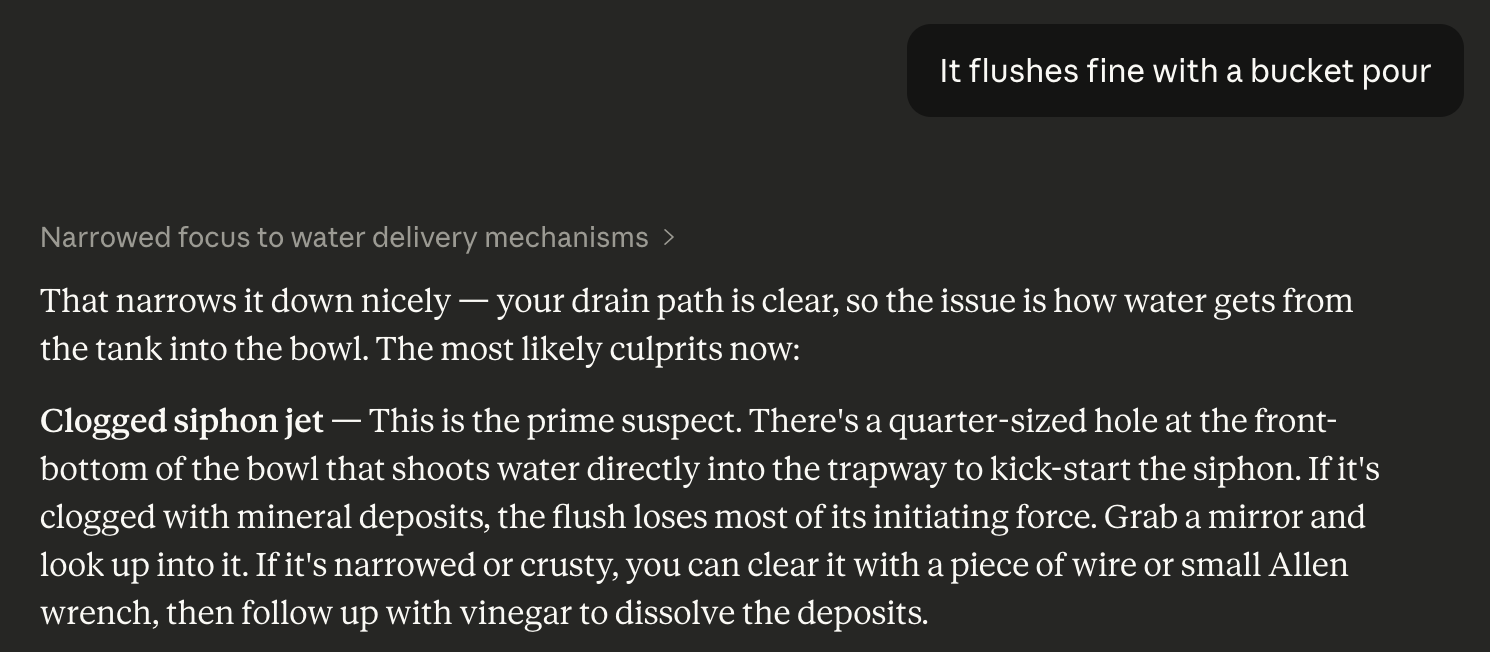
This is a suggestion I love as an engineer–it’s the core of good debugging. Isolate what my be the problem. I grabbed a bucket and did what Claude suggested, and was thrilled to watch the toilet execute a hearty flush. Huzzah! So now it’s time to look into this mysterious “siphon jet, what’s that anyway?”
Friends, I did exactly what Claude told me and it completely fixed the toilet. I felt like a hero, surging with a sense of accomplishment and DIY glory that was really not much dimmed by the fact I just did what an LLM told me to do. This took just three turns with the LLM to get exactly the fix I needed.
I’ve come to learn coding with Claude every day that this is what LLMs truly shine at–instantly bringing in the correct context to solve a problem that many other people have already solved and (critically) talked about the solution to on the internet.
Things were not so smooth for my next fix… although I ultimately prevailed.
Part 2: The Microwave
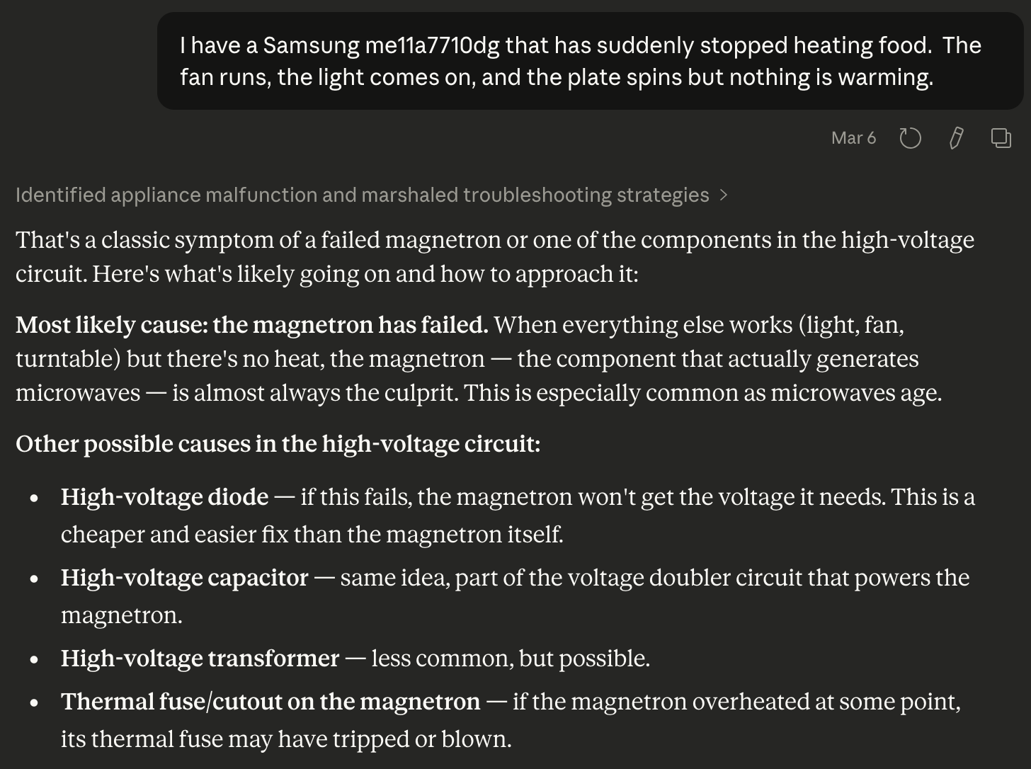
A few days later, Leslie complained that the microwave wasn’t heating things. Sure enough, when I observed it, everything seemed to be going right, with lights on, timers counting down, fans running–but it lacked that low rumble I was used to hearing and things were just not heating up.
My first instinct, confirmed by my fellow EE undergrads, was to chuck it and get a new microwave. This is because microwaves have high voltage parts inside that can kill you really good, in particular a high-voltage transformer hooked up to a high voltage capacitor that brings things up to about 4000V. But this was a fancy microwave, bought to match the range it’s installed above, so it was expensive (about $700) and maybe impossible to find in the same matching color.
It was time to talk to Claude about it:
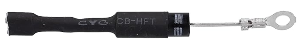
Let me spoil things a bit and say that in the end I did fix the microwave, and Claude here named one but not both of the parts that had failed (the high-voltage diode). Claude’s great failure was that it never suggested the other failed part, even after several hours of debugging across several days, and only because I had some background in circuits was I able to figure it out.
I started by going through diagnostic procedures with Claude’s help on all of the high frequency parts. The expensive stuff seemed okay, but when I got to the diode (a passive circuit element that allows current to flow one way but not the other), I found that it was open (it let current flow both ways). Bingo! Surely this was it, Claude was very confident in the fix, and I managed to order the part overnight from Amazon.
This thing just took a pair of pliers and a screw driver to replace, and of course an encounter with the potentially-deadly high voltage capacitor. I got it installed, closed up the case of the microwave, and put in a mug of water for 30 seconds. To my great disappointment, it still didn’t work–still missing that low-frequency hum that showed the magnetron was running.
The limitations of LLMs
I was bummed. After my slam-dunk success with the toilet, I felt invincible, and like with Claude as my co-pilot, I could get through any home repair issue. But I was at a dead end. I spent another couple of hours debugging with claude, working over every component in the high-voltage circuit with my multimeter and confirming they were all working as expected. It was just where you don’t want to be in a debugging effort–all the parts verified working, but the system as a whole broken.
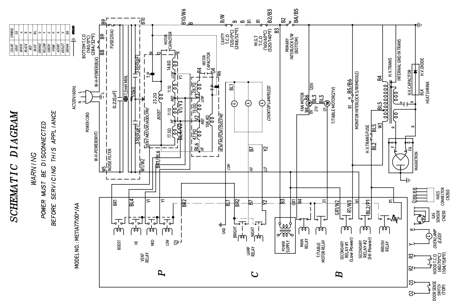
In desperation, I pulled up the circuit diagram of the microwave that was included in the service manual I’d paid for so I could be sure about which screws to take out to disassemble it. Here’s what I was looking at (yes, it was sideways in the PDF):
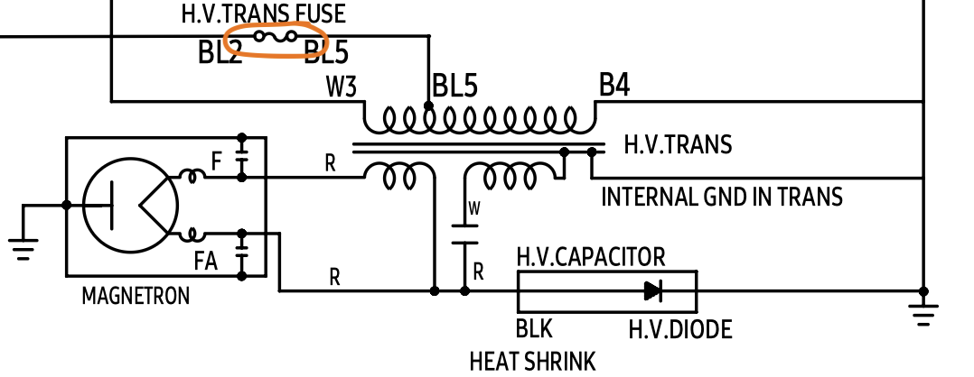
I found the little section on the right with the high voltage components, all of which I’d tested… except one. A fuse, circled here:
This was the second broken part. Claude had never mentioned this fuse, so I hadn’t tested it. I was on rails, under the confident guidance of the LLM. I was lucky to have training in electrical engineering and experience reading these diagrams–without that, I never would have solved my problem, and the microwave would probably have gone to a landfill.
To me this captures perfectly the magic and limits of LLMs. I was right where LLMs shine with the toilet repair–a simple machine, a common failure mode, probably written about thousands of times in the training data, aka the whole damned Internet. But with the microwave, things got too specific. Claude knew in general how microwaves worked, what parts they had, even how to test them. There were forum posts about repairs to similar microwaves. But knowing about the specific parts of my specific microwave, and how they might be implicated in the failure–this was just too fine a detail for the probabilistic completion machine that is the LLM. When the right answer to your question is becomes sufficiently unlikely, an LLM can never produce it.
Things heating up again
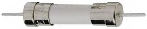
It took three days to get a replacement fuse, because this was not a fuse meant to be serviced–it was through-hole soldered, and for a high-voltage circuit. But once it came in, I soldered it in, reassembled the microwave, and bam, water was heating again!
Although we don’t think about it much, indoor air quality matters. We spend most of our time indoors, breathing whatever is floating around. And because our houses are full of humans, that means dust, dirt, carbon dioxide just from us being gross; also things like volatile organics, combustion byproducts, and mold that come from what our houses are made of, what we do in them, and what likes to live in them with us.
Historically, this was tolerable because houses were not very “tight:” they had natural cracks and gaps in the walls that let in plenty of fresh air. But modern building practices have changed that: houses are made very energy efficient through things like spray foam insulation, complete water-tight envelopes, and tightly sealed windows and doors. This often has the side effect of severely limiting air exchange between the interior and exterior of the house, so indoor pollutants can build up inside.
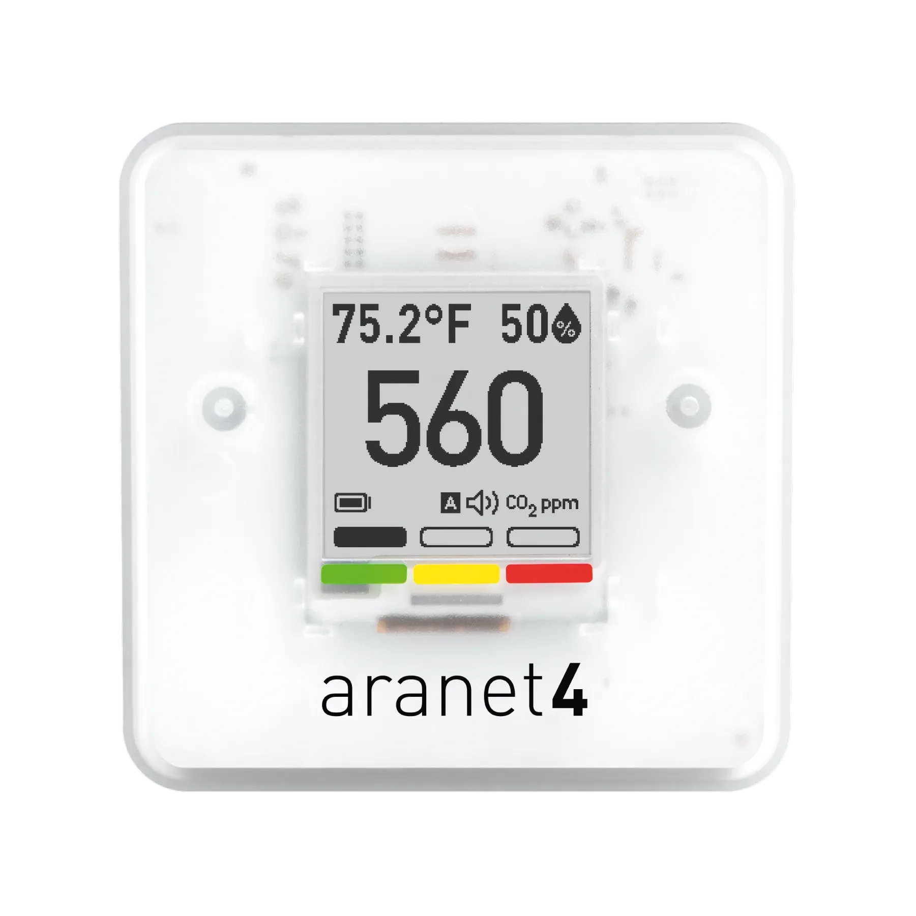
Most people would read about this and shrug, because it feels like we are all doing fine breathing whatever air we’ve got. But not me! I’m constantly on the lookout for things to worry about, so a few years ago I started buying carbon dioxide monitors so I could torture myself with a constant feed of air quality data. I really like the Aranet4 CO2 monitor, I now have three of them in the house.
The e-ink display is classy and the battery lasts more than a year
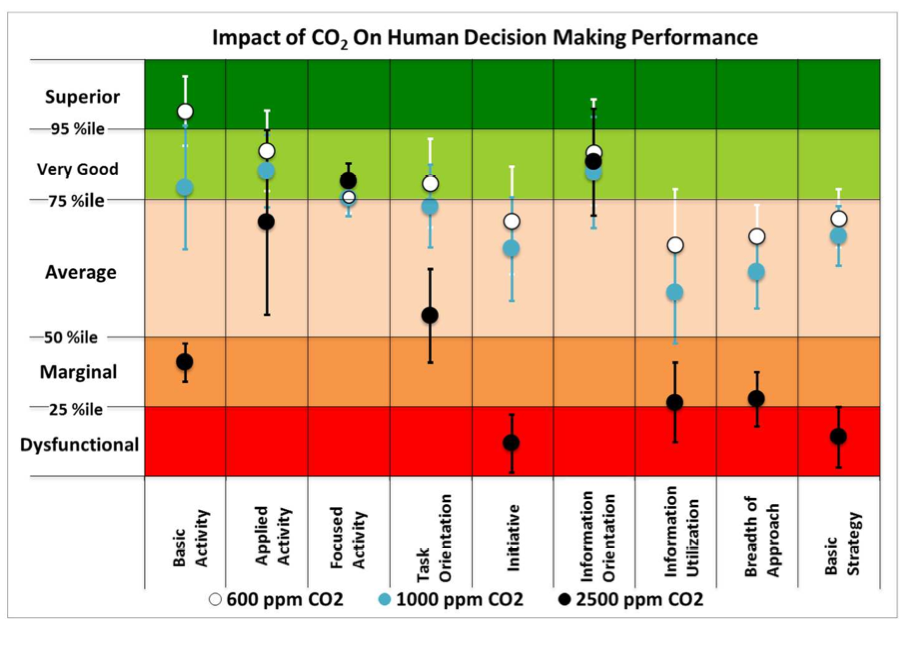
While it can be very expensive to buy monitors for the many varieties of indoor pollutants, it turns out that carbon dioxide is a great proxy measure. Humans are always exhaling it, so when its high, it’s a good sign that the air is stale and probably contains high levels of other pollutants. Plus, studies show that levels of CO2 frequently observed in indoor environments have measurable impact on cognitive performance along with unknown long-term side effects.
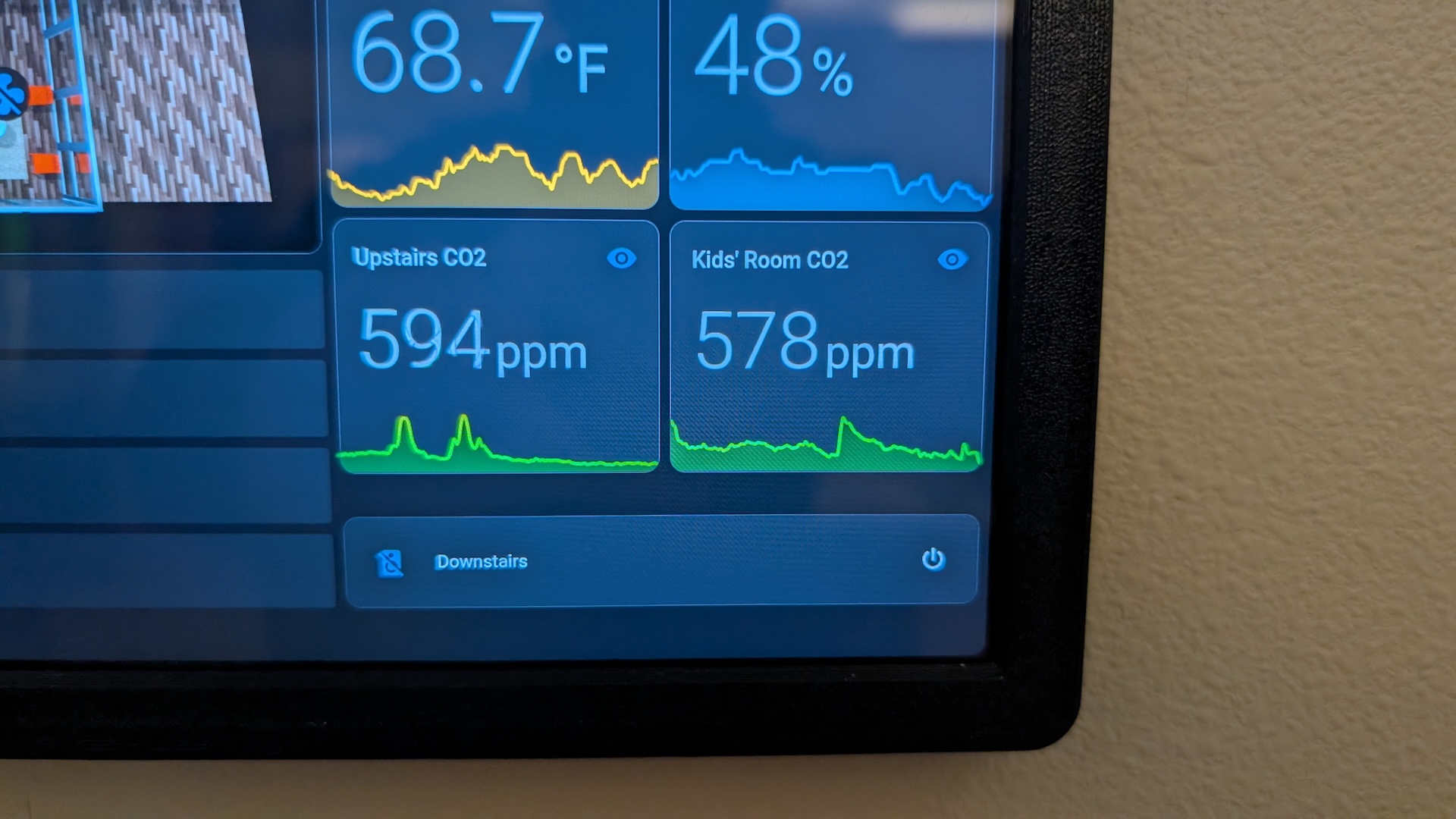
A critical aspect of the Aranet monitor is that I can integrate it via Bluetooth with Home Assistant, my centralized home automation platform. This integration allows me to produce horrifying graphs of the CO2 levels in my children’s bedrooms
This is not ideal.
I’ve been watching these numbers with simmering dismay for a couple of years, not really sure what I should do about them. For reasons I have not been able to figure out, the levels are worst in the shoulder seasons, when the AC and heat aren’t running very much. Running the AC or heat seems to drive the levels down, somehow bringing more fresh air into the house. When CO2 is hatruly high, I can always open a window. But the manual nature of that just doesn’t appeal to my sense of sustainable problem solving.
This fall, after watching the high CO2 levels night after night, I decided to act–I was going to find a way to get more fresh air into the house.
The Solution: automated fresh air with an energy recovery ventilator (ERV)
So how can we improve on an open window to let fresh air in and stale air out? First, we could open two windows, so that a breeze could blow air through the house. That gives you an inlet and an exhaust, but it depends on the weather how much air turnover you actually get. And oh, the weather: that’s the other problem with opening windows. In Austin it gets hot in the summer and we use energy to cool and dehumidify the indoor air. Open windows just bleed out that conditioned air.
The home HVAC industry has devised a solution for this: an energy recovery ventilator. This is a box that pumps in fresh air from an exterior vent and dumps it into your house, while pumping stale air from an interior vent and dumping it outside. The energy recovery part is that the incoming air and outgoing air pass by one another in a lasagna-like heat and humidity exchange manifold called the ‘core,’ so the incoming air ends up with similar temperature and humidity to what’s already in the house. This saves energy (about 75%) that would otherwise be spent conditioning all the fresh air brought in Here’s a video from This Old House that explains it:
ERV install options
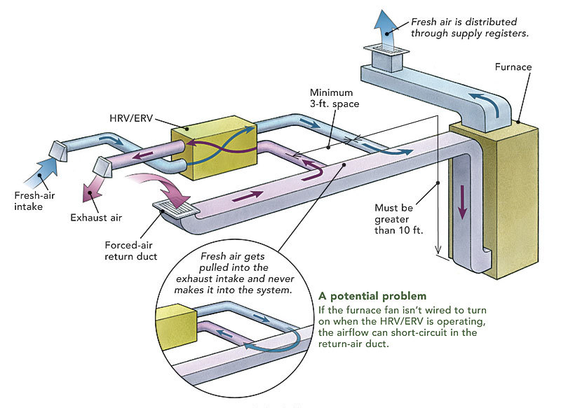
It seems intuitive that if you already have a ducted HVAC system, you’d want to reuse those ducts for the ERV. Maybe you could tap into the return ducts to pull stale air out of and then splice the fresh air into output. But it’s a bit tricky: the HVAC ducts and air handler are usually a closed system (they just recirculate interior air, optionally heating or cooling it). The ERV pulls new air from the exterior and pushes old out. If you try to run the ERV using the same ducts, you have to coordinate the HVAC fan so it runs at the same time, or else you’ll be fighting that system. In the worst case, you might cause condensation to form in your ducts, and you’ll probably also have to overspec your ERV fan so that it can deal with all the ducting pressure.
Intuitive but suboptimal: reusing your HVAC ducting for your ERV. (from finehomebuilding.com)
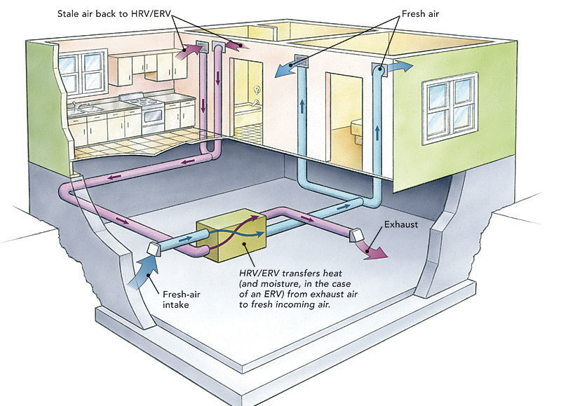
The whole nine yards: multiple dedicated ducts. (from finehomebuilding.com)
My compromise for DIY ease: separate ducts; single input and output
There’s no chance of running a full set of dedicated ducts like the one in the second picture in my house. The existing HVAC ducting is squeezed in between the floors, inacessible with no room for expansion. Plus, the more holes I have to cut in walls and the exterior the less realistic this becomes as a DIY job. However, I happen to know that air circulation within my house is good by watching CO2 monitors placed upstairs and downstairs: they hardly ever diverge, even when everyone in the house is downstairs.
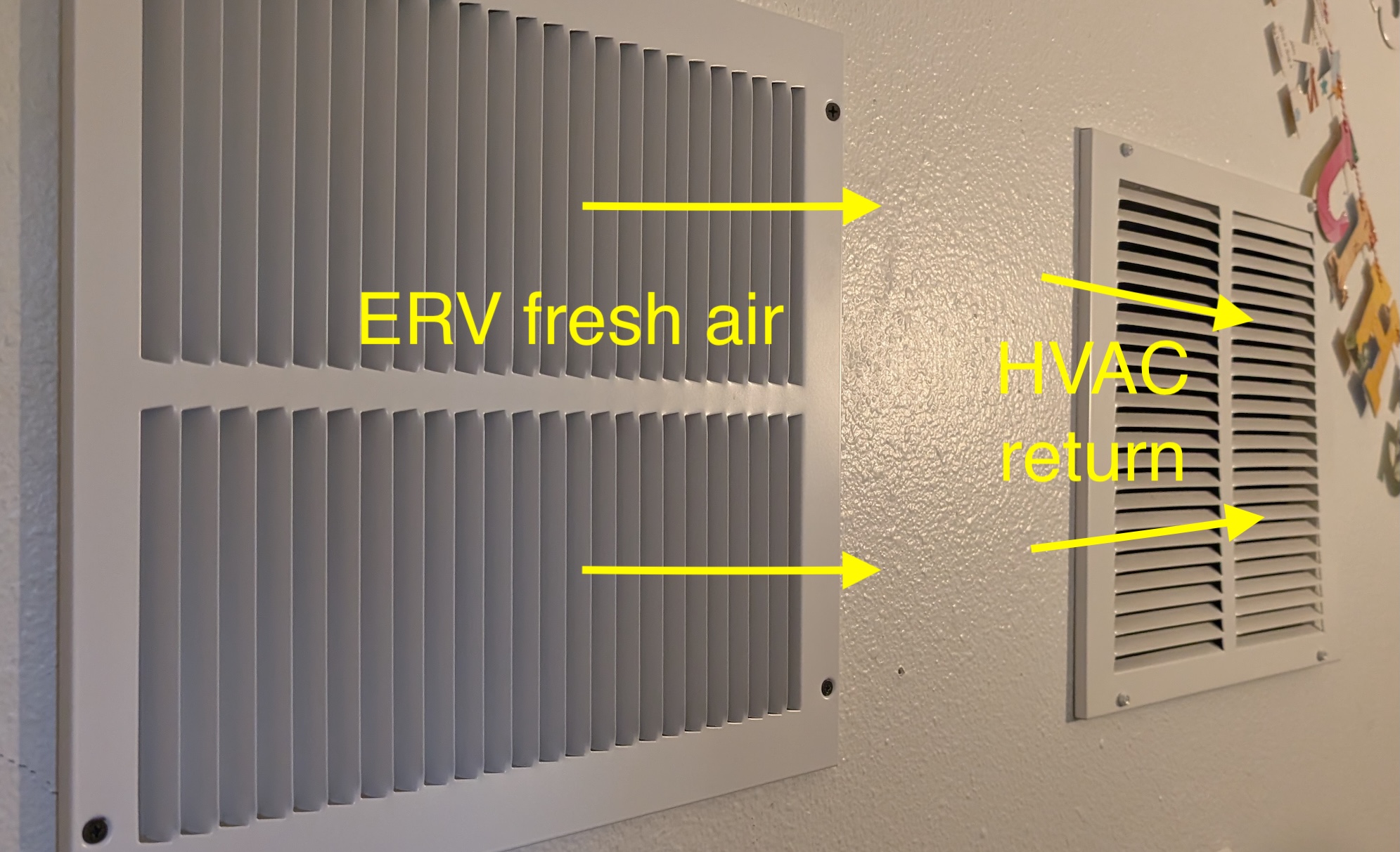
So, I reasoned I could probably get away with one big vent pulling stale air from the interior and one big vent dumping fresh air back in, especially if I was a little clever about it. I decided to pull air out of the kids bathroom, above the shower, and dump fresh air into my office right next to a return air vent. This is akin to tying the fresh air into the return air duct directly, but without the pressurization / fan synchronization issues. I run the HVAC fan for recirculation 30 minutes of every hour, so there should be plenty of time that the return is pulling fresh air from the ERV and redistributing it throughout the house.
My DIY compromise fresh air delivery
Combine this with the fact that the attic over the old part of the house already had two 12"x12" gable vents that I could reuse for exterior intake and exhaust, and I only had two cut holes (both interior) for the whole project!
Here’s a sketch of my final design:
The ERV is connected via 8" flex ducting to each of the attic gable vents and to the interior and to two interior 12"x12" vents, which are a bit oversized but the goal is for them to be silent when the ERV is in operation.
Shopping list
The ERV
There are a ton of ERVs on the market; the main difference among them is how much air they move. They typically have four ports (exterior fresh air in and stale air out; interior stale air in and fresh air out). I selected the Broan One (model BLP150E75NS-PC) because it has constant, automatic pressure balancing to make sure the amount of air it puts into the house equals the amount it pulls out, even when things change like a window opens or a bathroom fan comes on.
It has a middle-of-the-road air movement capacity of 150 CFM, more than big enough for my 2700 sqft house, especially because of my weirdo plan to have just a single intake and exhaust. It has simple washable filters (you can optionally add MERV) so ongoing costs should be low.
The Broan “One” series is a bit cheaper and much less diverse than the “AI” series which come in many physical port configurations and CFM ranges; the “One” series seemed to have the same auto-balancing brain and was released more recently. I also considered the Panasonic Intelli-Balance ERVs but they lack the automatic balancing and require more skill and equipment to “commission” (get the input and output airflow balanced for your house).
Price: $1056
The Rest
Here’s all the sundry items I needed to accomplish the install. I ordered the ERV online and bought the rest from Home Depot–I bet I could have gotten better prices from an HVAC supplier but most of them aren’t interested in a DIY-scale customer like me. Still, the overall price came in under $1700. The quote I got to install an HVAC-integrated ERV started around $4k. That actually sounds about right given the expertise required to do this right, including the system design, plus overhead.
Name
Pic
Description
Price
Qty
Total price
Broan BLP150E75NS-PC
The actual energy recovery ventilator
$1,056.52
1
$1,056.52
12"x12" to 8" register box
For duct terminations
$21.90
4
$87.60
12 x 12 inch return air grill
Covers interior vents
$15.98
2
$31.96
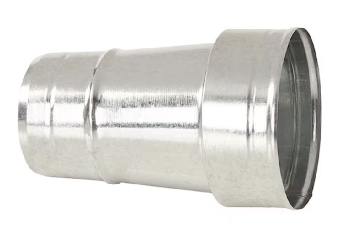
8 in to 6 in reducer
Convert 6" ERV ports to 8" ducting
$14.28
1
$14.28
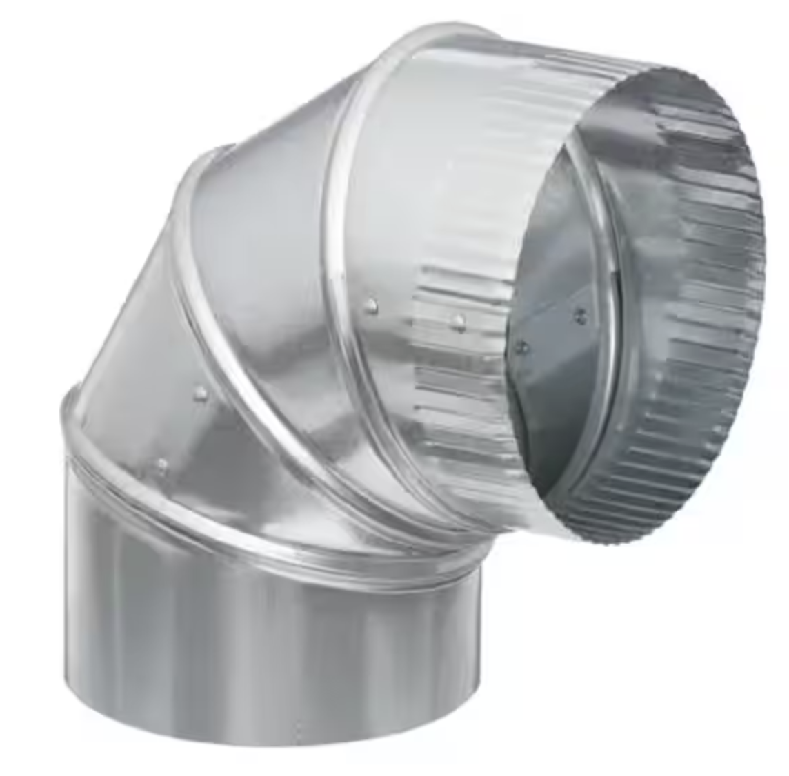
8" 90-degree ell
To improve airflow when a bend was necessary
$8.90
3
$26.70
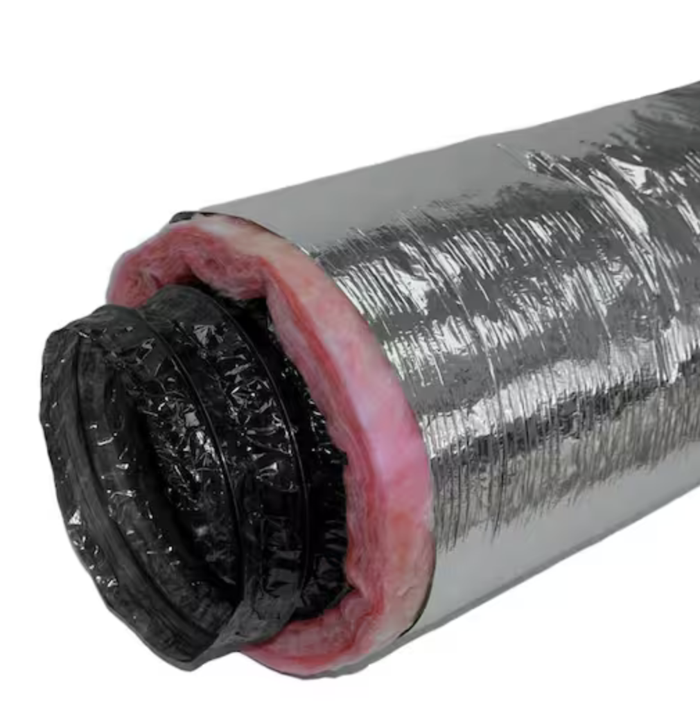
8" R8 insulated flex duct, 25'
For moving air to and from ERV
$102.00
3
$306.00
555 FlexFix tape, 1.89" x 120 yd
For connecting flex duct interior
$14.98
1
$14.98
324A Foil Tape, 2.5" x 60yd
Heavier foil tape for sealing
$23.97
1
$23.97
Foilmastic Tape 2" x 34 yd
For sealing seams in metal ducting (instead of mastic)
$29.98
1
$29.98
36" nylon ties (25)
For securing flex duct to collars
$17.90
1
$17.90
zip-tie tightener
For tightening big zip ties
$57.00
1
$57.00
Grand total
$1,666.89
The install process
The biggest adventure by far was getting this thing into the attic and ducted. I watched many Youtube videos on how to work with flex duct, how to connect and seal the ductwork, how to spec size and length. I was shocked just how much disagreement there is about something as simple as how you connect the end of a piece of flex to a ceiling register–some people put mastic inside, some don’t; some people use zip ties, some use mylar tape, some use both. In the end I followed the instructions that came with the ERV: I used a zip tie on the interior liner of the duct plus mylar flex tape to seal it, then another zip tie around the insulation and more tape just to clean it up.
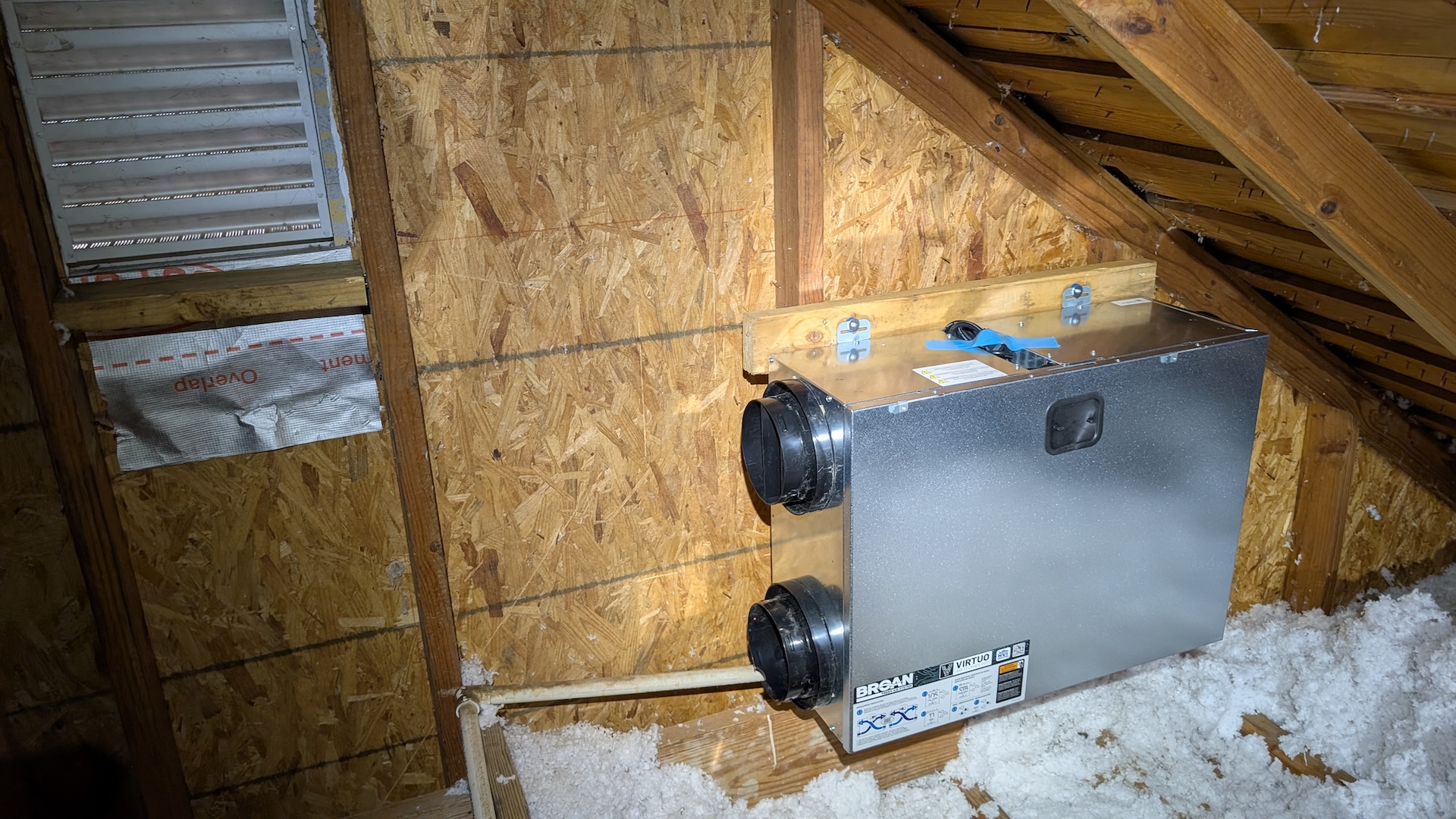
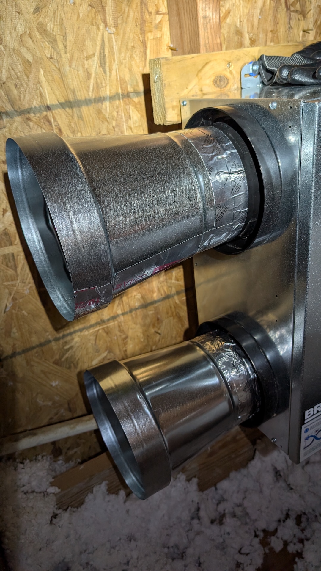
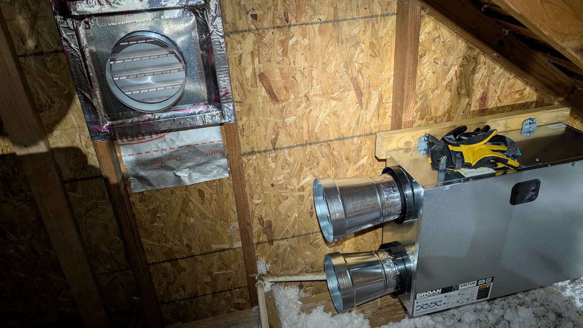
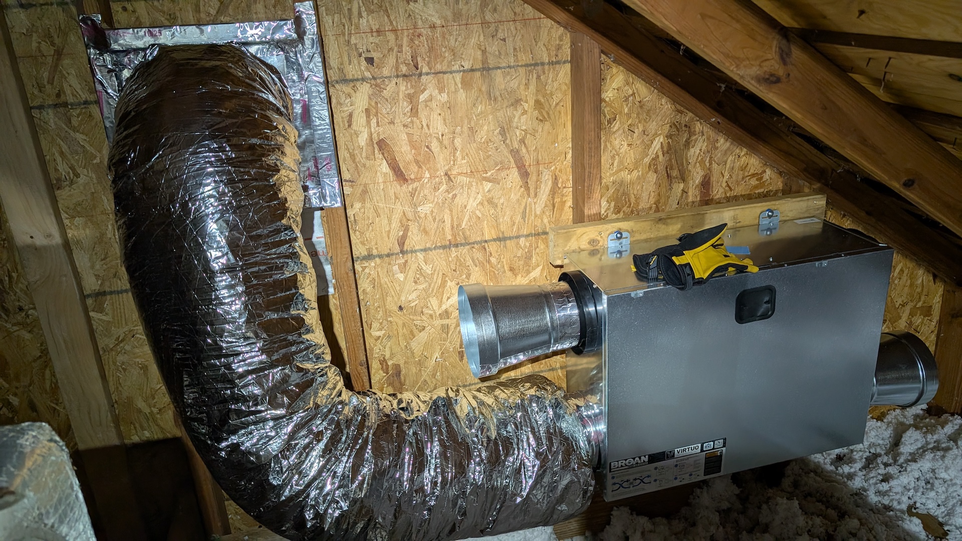
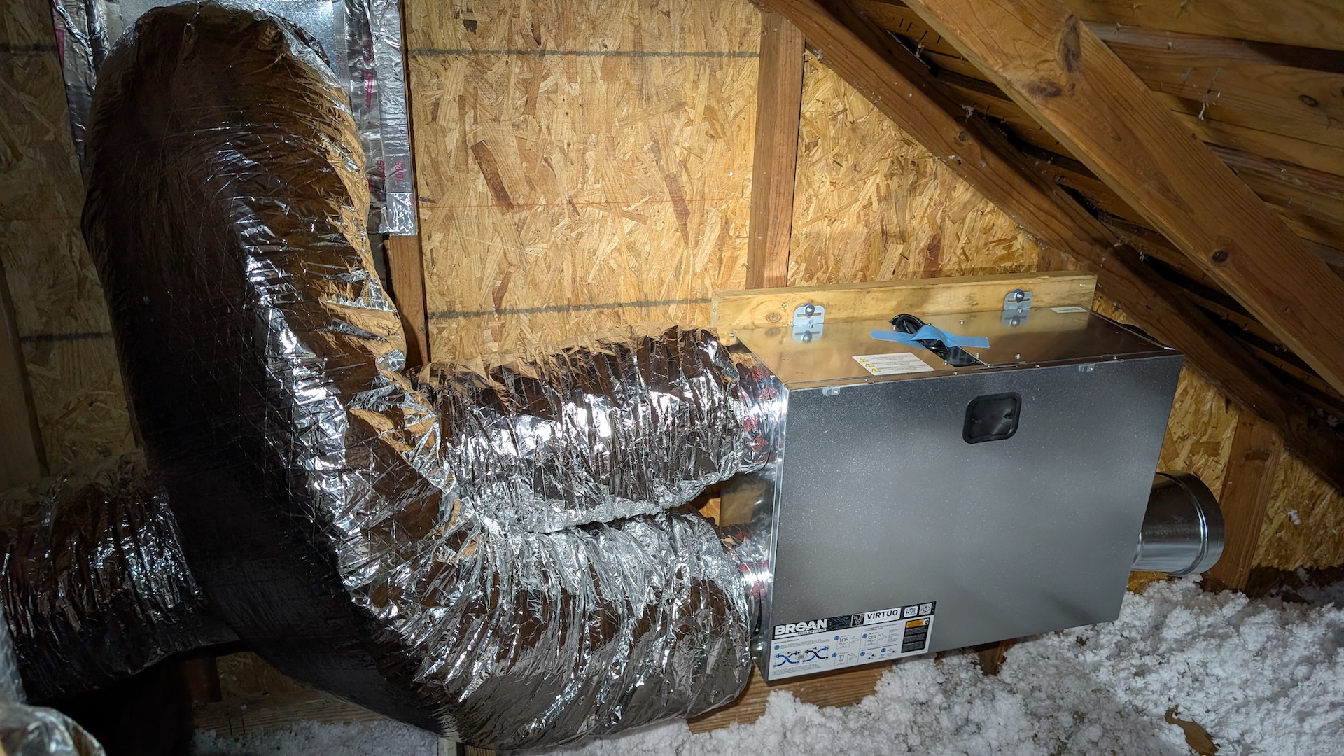
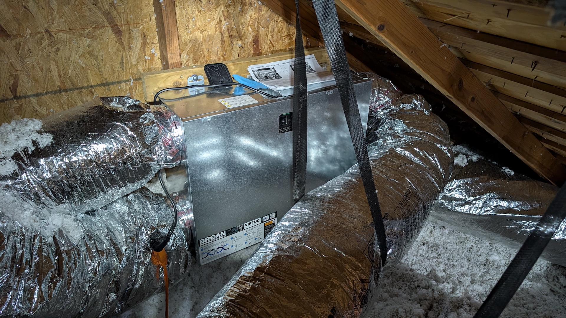
Here’s the ERV after I lugged it up to the attic and screwed it into the frame I built to mount it on:
You can see the interior side of one of the attic gable vents I used. Because I used 8" ducting and the ERV has 6" ports, I needed to adapt the sizes, so I started out by attaching 6" to 8" increasers on each of the ports using foil mastic:
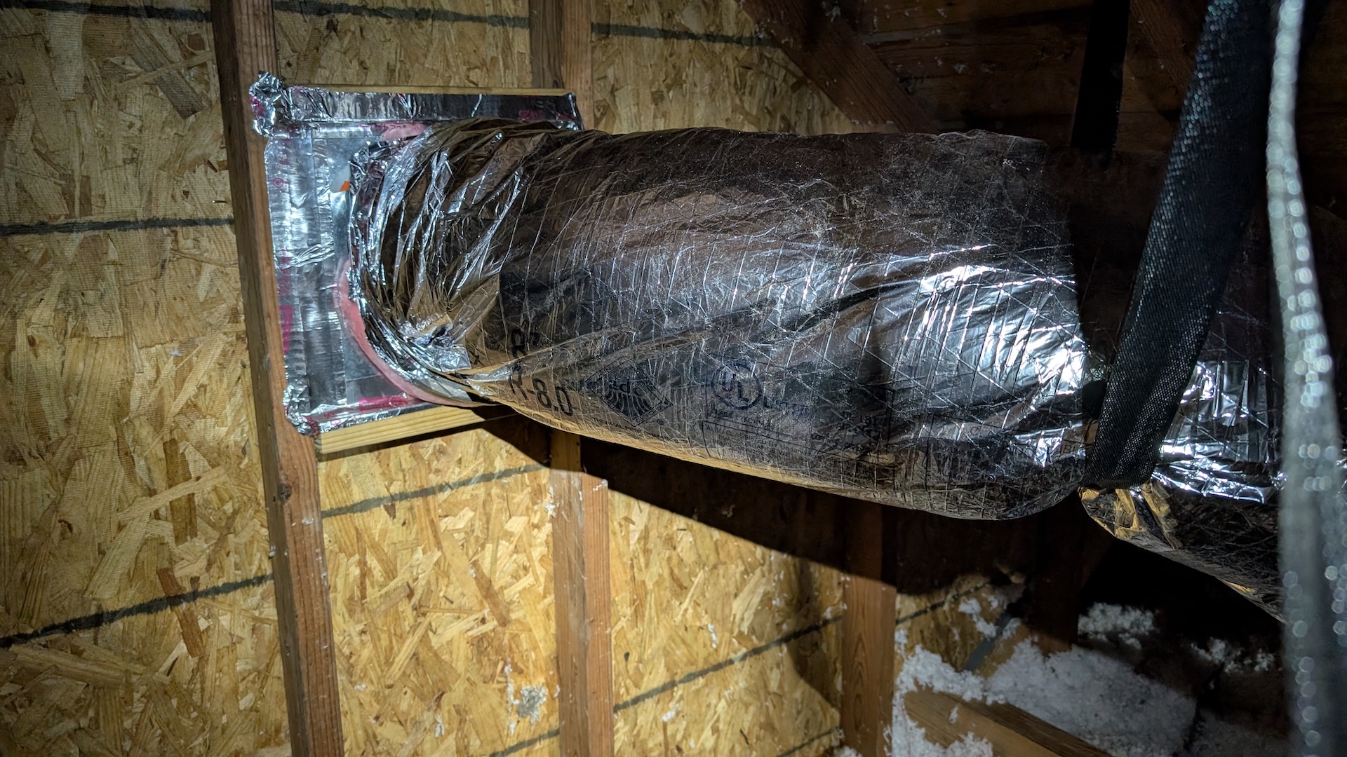
Next, I framed up the gable vent with an 8" round to 12" square register boot, just going absolutely nuts with foil tape. I love that stuff:
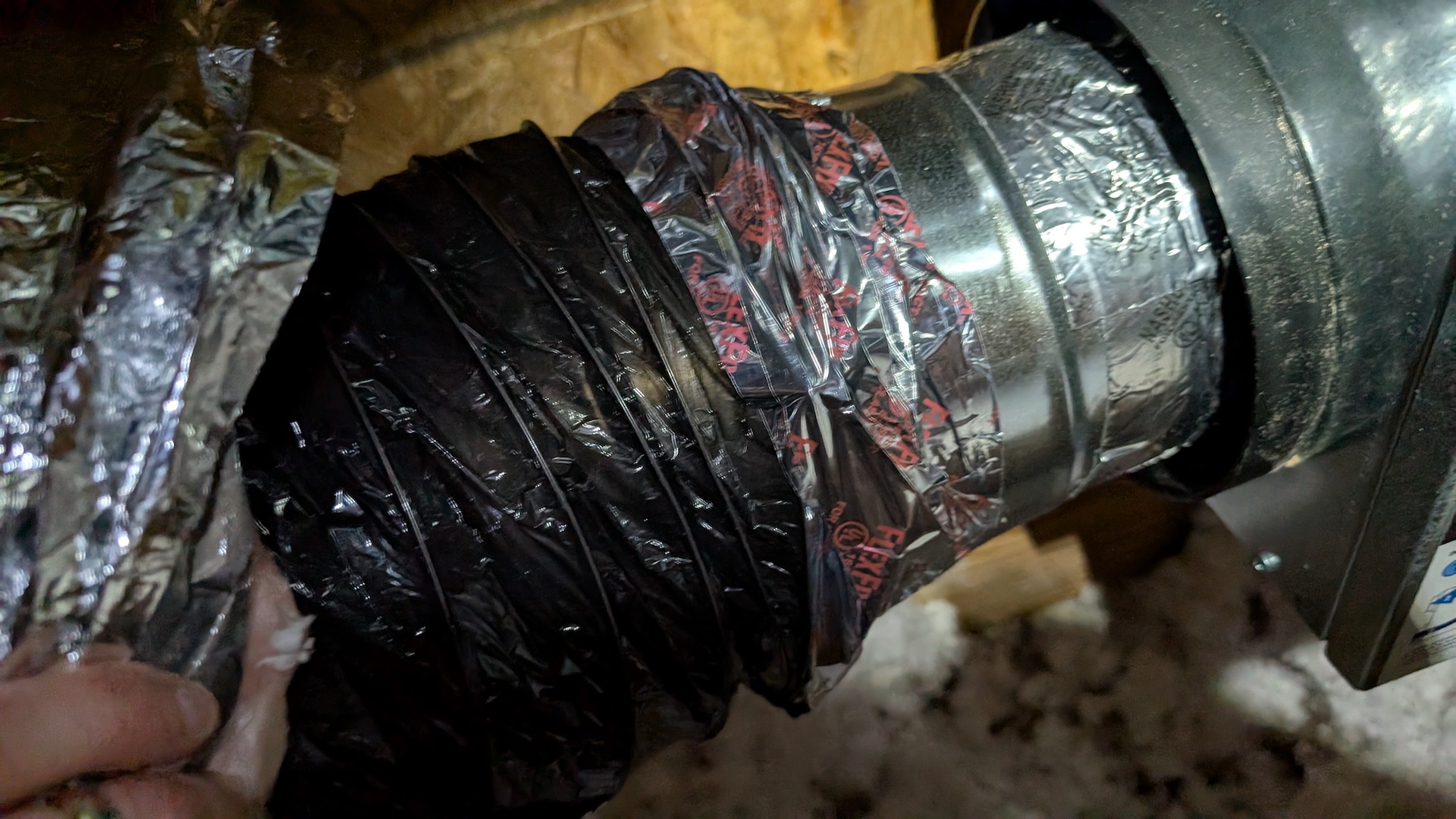
I attached the flex duct using the belt-and-suspenders approach of placing a zip-tie on the inner liner, then using flex duct tape (a sort of thin mylar variant of the foil tape), then pulling the insulation down around the collar, and zip tying and taping that. Seems totally bomber, like you could rip the collar off the ERV before this bond would fail.
Although it was almost certainly over-engineering, I used rigid 90-degree sections when I needed to turn the path of air in a tight space. The internet seemed to think this was important to avoid restricting airflow in the flex, which tends to sort of collapse if you take it through tight turns.
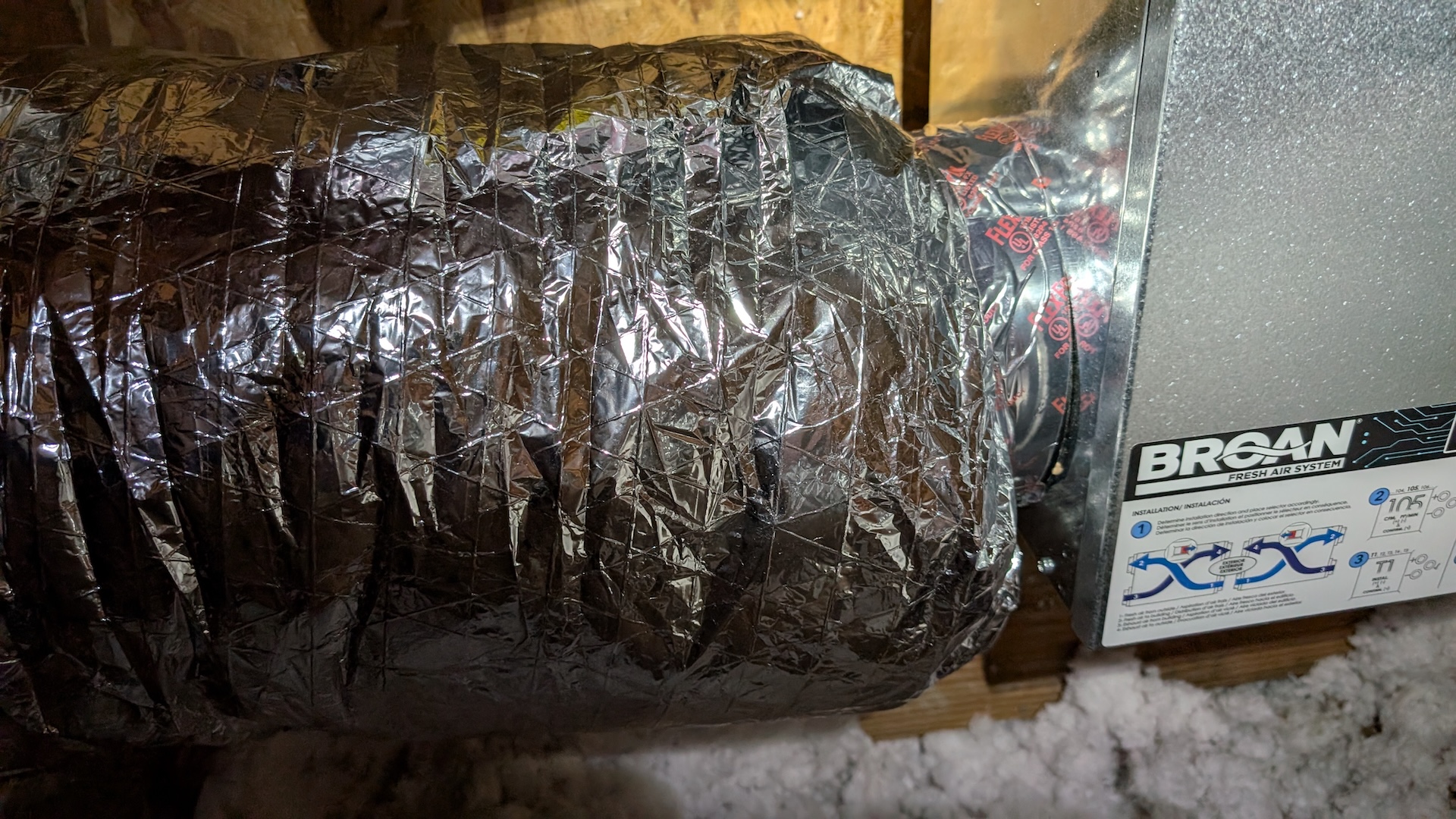
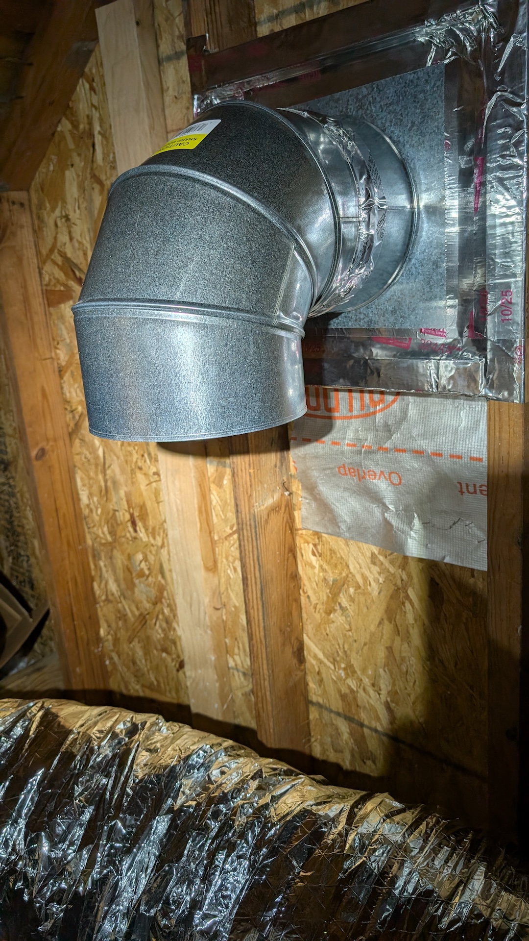
Here you can see the first of four connections to the ERV complete: the air path from the gable vent to the input of the ERV, which draws fresh air in:
The second gable connection takes stale air out of the house; it was about 20 feet away from the ERV and pretty tricky to route around all the existing HVAC flex. I also got to try my hand at using these hang straps that are recommended to keep weight off the register connections and sharp bends out of the flex.
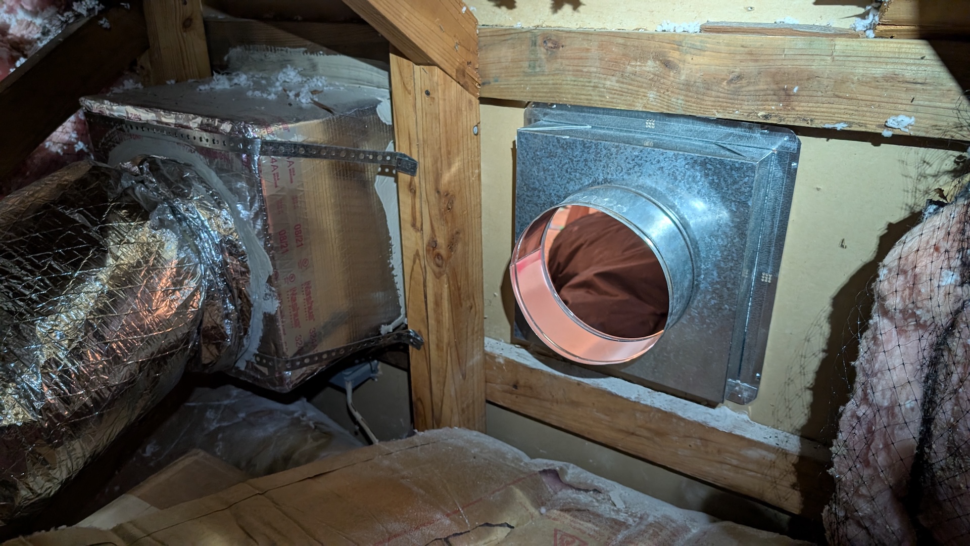
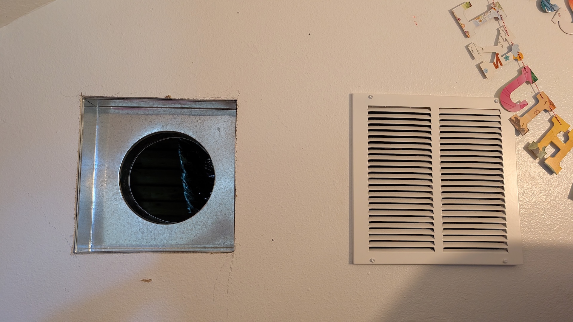
Next came the excitment of the interior connections, which required cutting two new 12"x12" square holes. I already discussed my decision to place the fresh air output right next to a return vent in my office. Here’s the view from the attic and the loft of that register going in:
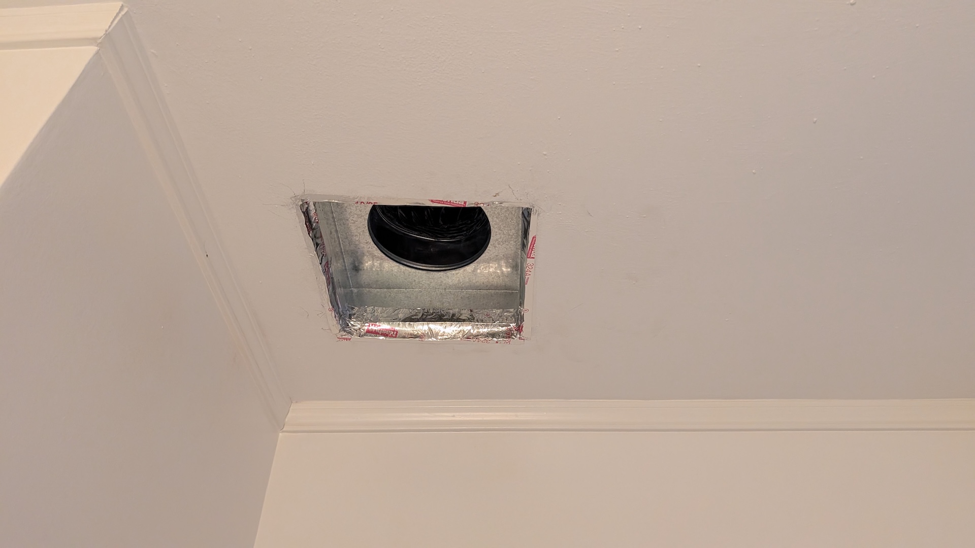
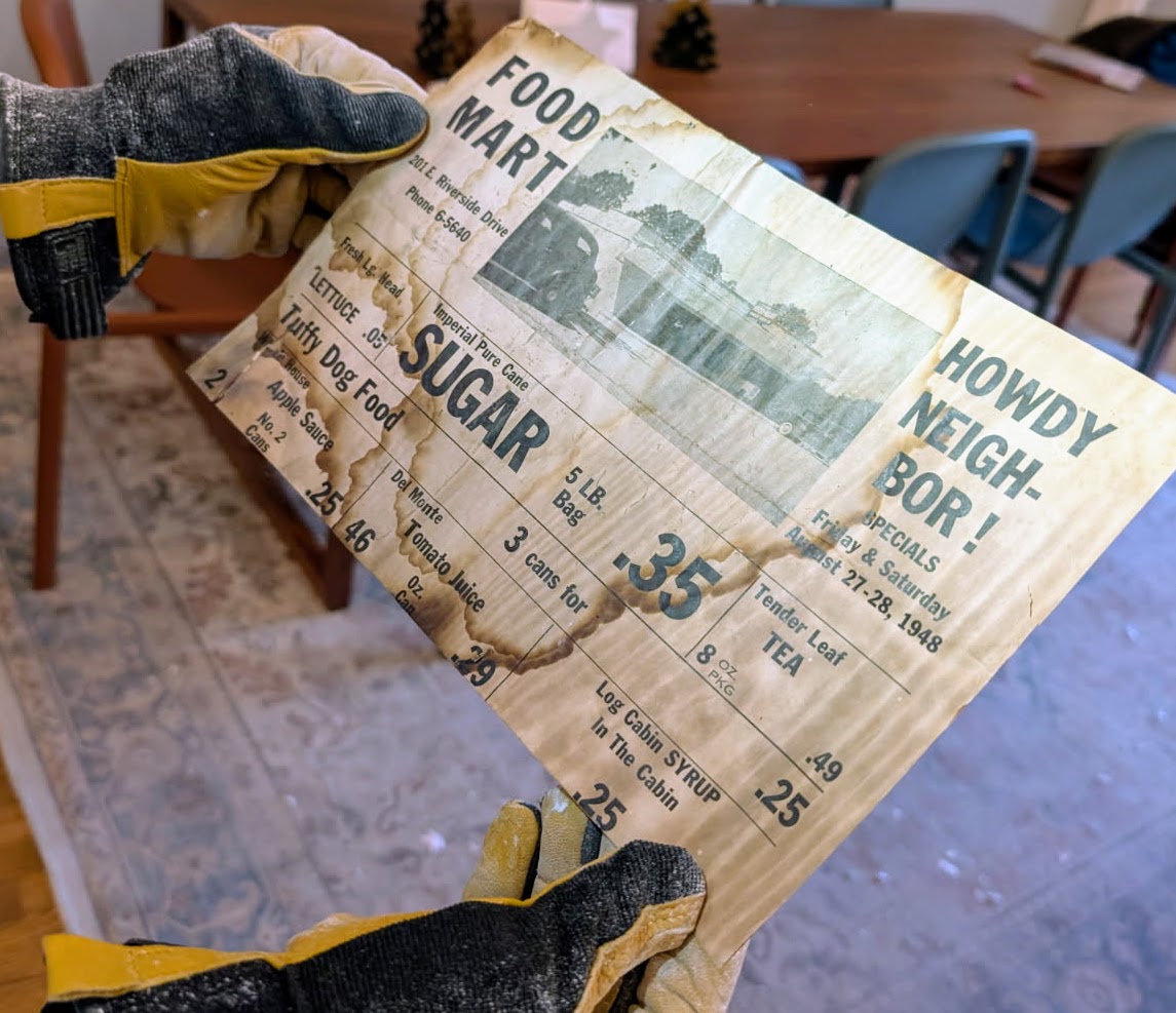
The stale air gets sucked from the ceiling over the shower in the kids’ bathroom. As part of this excavation I discovered some beautiful (not really) old wall paper that used to be on the ceiling as well as a grocery flyer from 1948:
Here’s how the final install looks–pretty crowded with all the flex but I was incredibly proud, and bore the injuries of a dozen scalp punctures from roofing nails and lungs full of aerosolized rodent poop and fiberglass (just kidding, I wore an N95 so the coughs only lasted a day or so):
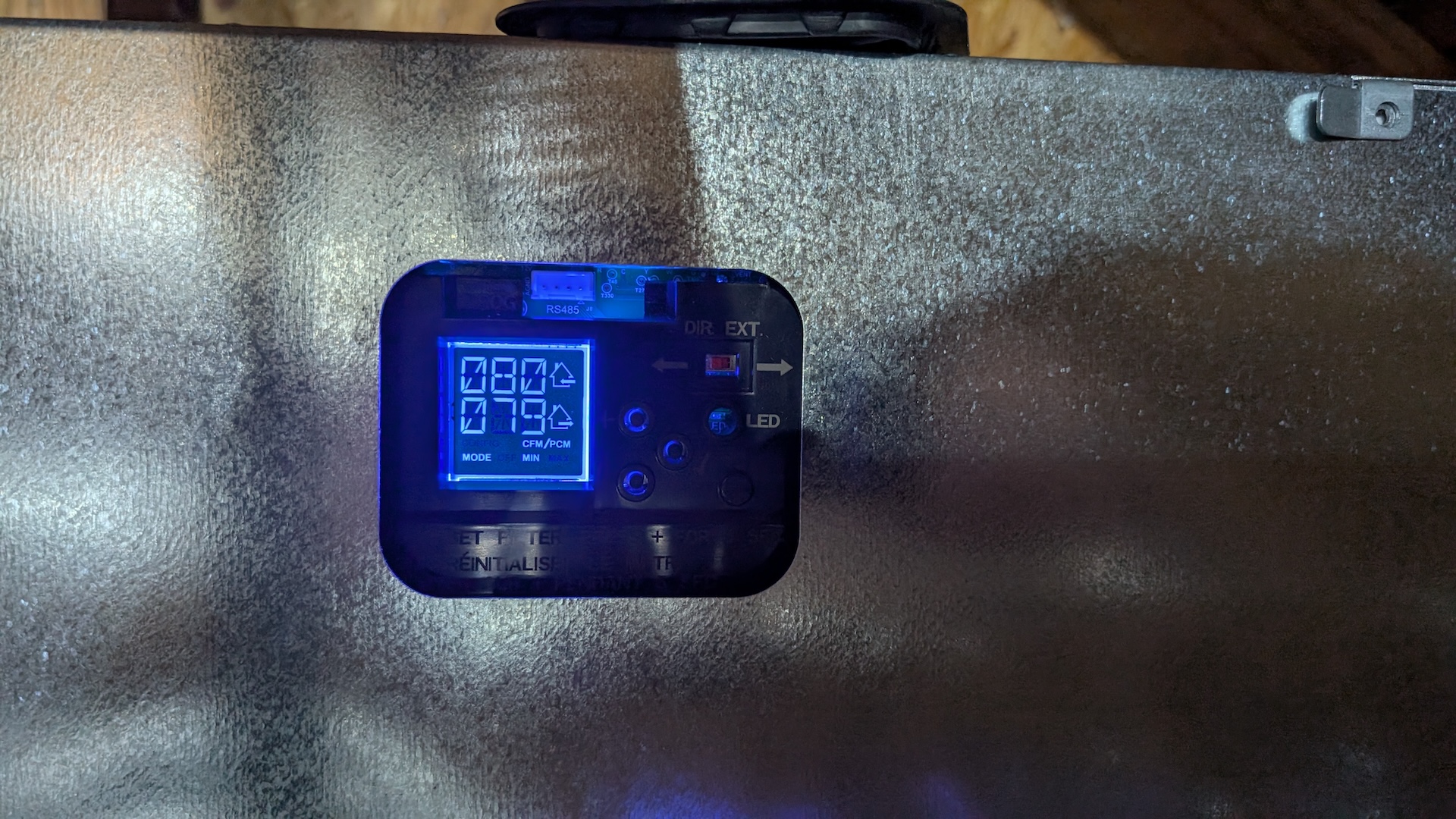
I plugged it in and was overjoyed to see it configure it self and report that it was happily running at low speed: 80CFM in and out in perfect balance!
And boy was it effective! After a few hours running at full speed, the CO2 was down at levels I’d only before seen after we’d been out of the house for days:
Connecting the ERV to Home Assistant
The final step in my adventure was tying the ERV into my smart home. Broan offers a bewildering array of wall control options, each offering a different subset of functionality to change how fast the ERV is blowing, how often in runs, whether it is controlled by humidity. I mean, there are at least nine controls for sale by them that work with my ERV.
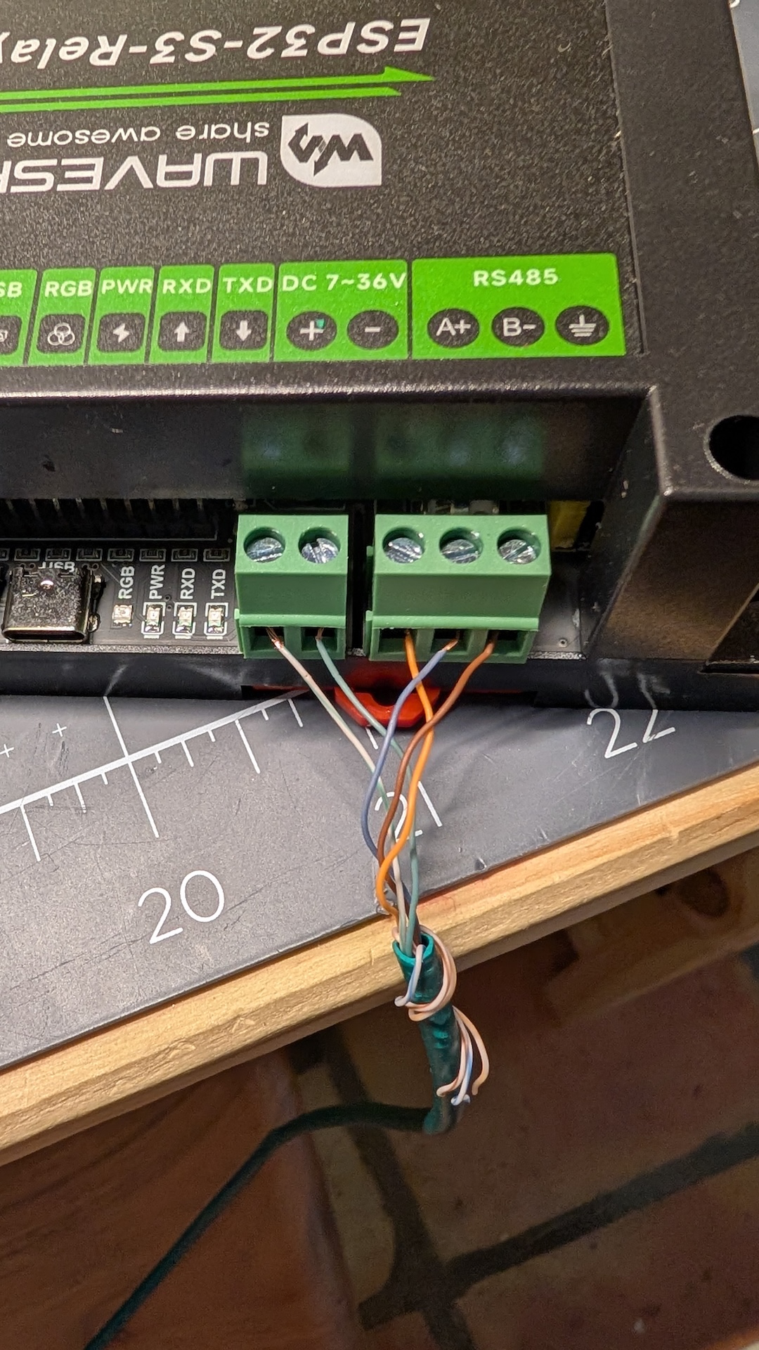
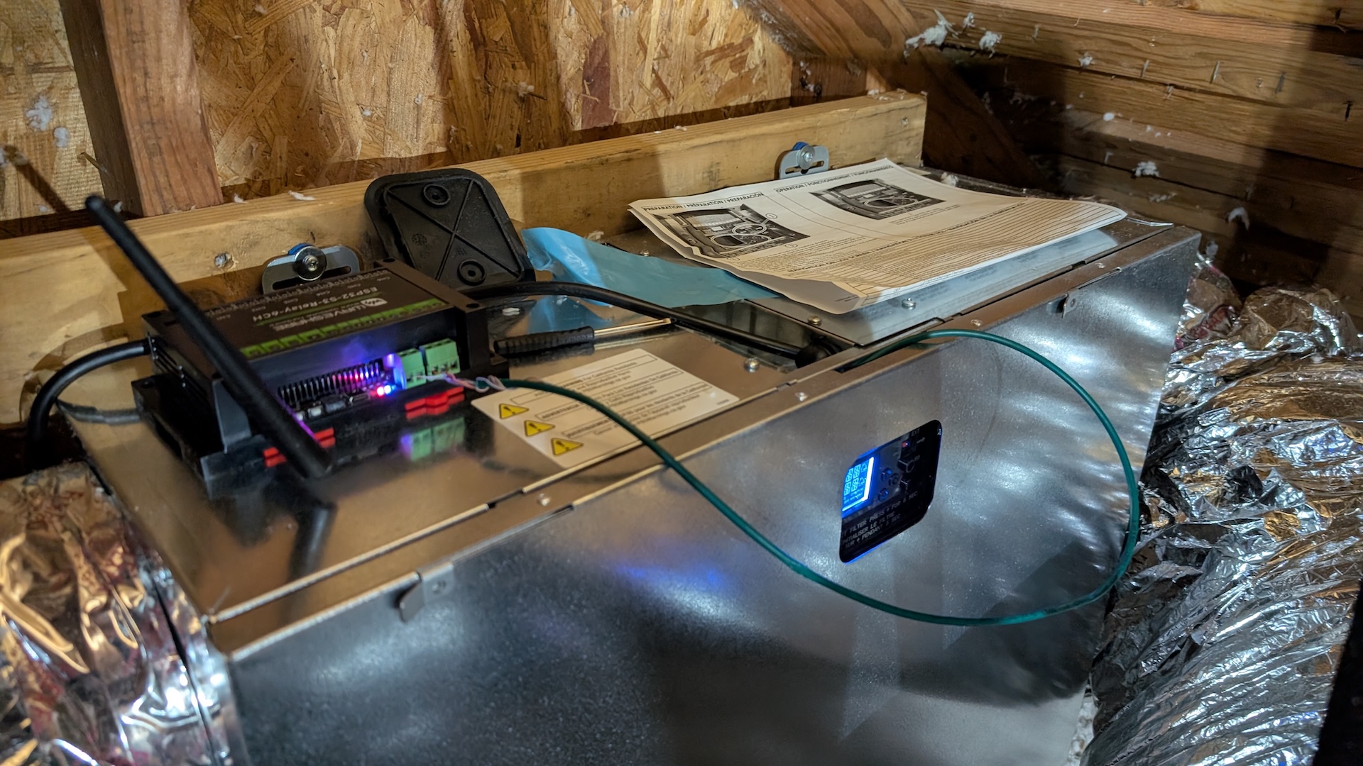
Instead, I wanted to hook this into my Home Assistant system so I could monitor and adjust it with the rest of my smart home stuff. The Home Assistant community totally came through for me: someone reverse engineered the RS485 serial protocol that the ERV uses to talk to the Broan controllers and implemented an ESPHome-based control for it!
I was able to wire it up directly to the 12 volt rail provided on the ERV, for a total of five wires: +12V, -V (tied to ERV ground), RS485 data+, data-, and data ground (tied to ERV ground).
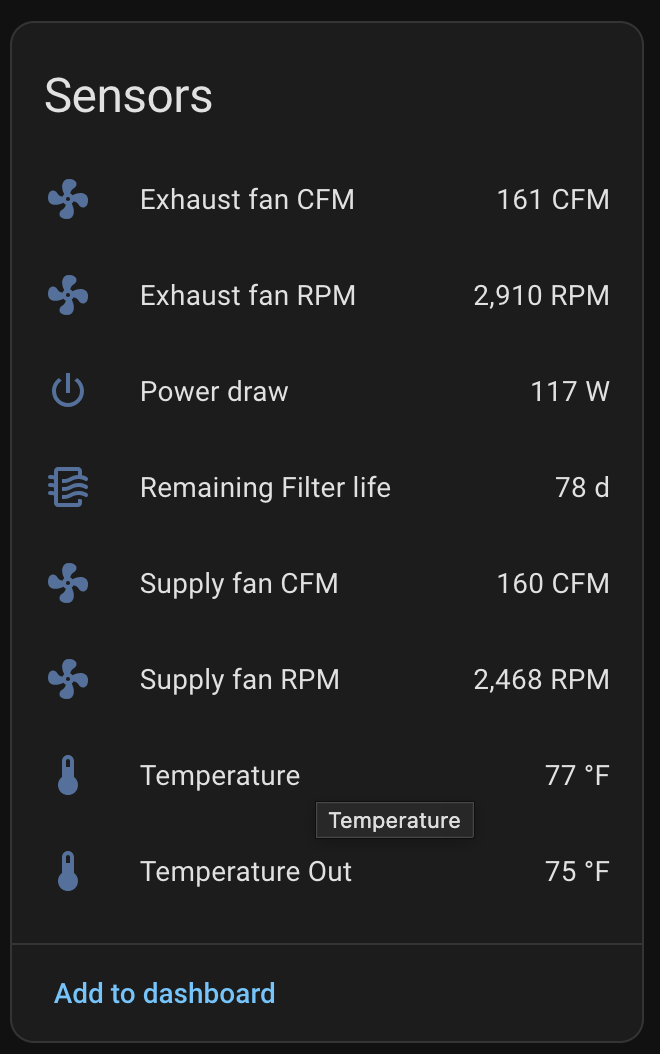
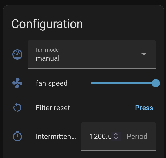
This was almost too easy, booting up on the first try and exposing lots of data and controls for home assistant:
So far, I have a simple timer that ticks the ERV up higher at night when everyone is home and turns it back down in the mornings. But in principle I could put this into a PID loop with the actual CO2 levels the Aranets measure—the sky is the limit with Home Assistant, as usual.
The results
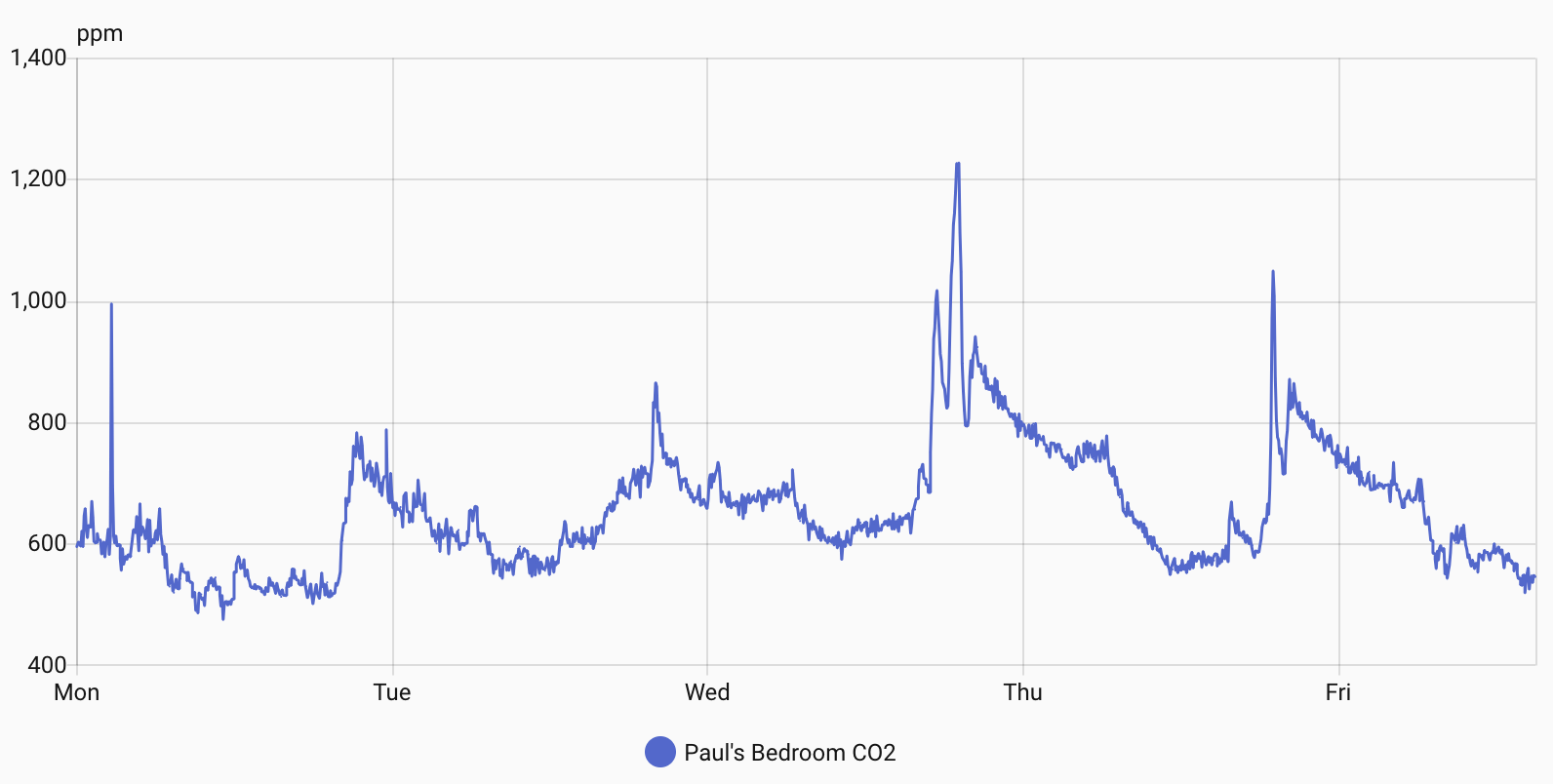
The ERV does its job well. Since I installed it, I seldom see CO2 levels rise above 800, even at the usual peak at dinner/bedtime. More often they hover in the 6-700s (six-sehhhhhhven), well into the range where I’m no longer worried about them. Here’s a plot of CO2 in Paul’s bedroom similar to the one at top. The spikes you see are when groups of people enter (usually kids playing). It’s so lovely to see spend almost all its time it down in the benign range.
A note about the site: I’ve migrated blog content for overt.org from Wordpress to Hugo. Hugo stores posts as Markdown and then converts them into static HTML for publication.
Hugo keeps things simple and lets me manage the content in a git repo. Of course, I had to convert from Wordpress to Hugo, but in 2025 that just meant a vibe-coded Python script from Claude Code that did a fabulous job of extracting all my embedded images and videos for the last 25 years, converted historical comments into Markdown, fixing many broken links in the process.
After extracting all the embedded images from Gallery (now hosted on Piwigo) I also decided to put gallery behind a password. Although it was getting 200k+ hits per day, I don’t think any of them were from people I know :) If you’ve known me for a while you can probably guess the username and password.
Some consequences of this migration are no more comments and no more search. But you you click the archives on the right you can search through the title of any post, and using site:overt.org on your favorite search engine is gonna work too.
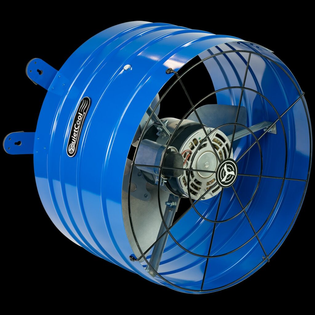
Fun little weekend project: I got a QuietCool AFG SMT PRO-2.0 attic gable ventilation fan that was “smart” in the sense that it came with a Bluetooth-based, proprietary app for configuring the fan with temperature thresholds, timers, etc. But I have an existing Home Assistant setup in my home, and for “smart” to be useful to me, it needs to show up in Home Assistant as a switch that I can turn on and off in response to the many sensors I already have configured there.
The fan itself
I was pleased to learn that the “smart” controller used for this fan is an ESP32, which means that a robust open-source ecosystem exists to replace its firmware with something that works directly with Home Assistant. Even better, it has a Wifi controller on-board, even though the fan controller is sold as a Bluetooth-only.
I found these excellent instructions for flashing the fan with Tasmota, an open-source firmware that is more general purpose and not natively integrated with Home Assistant.
Instead, I wanted to use ESPHome, a system that uses YAML files to declare what sensors and actuators are available and integrates natively into Home Assistant.
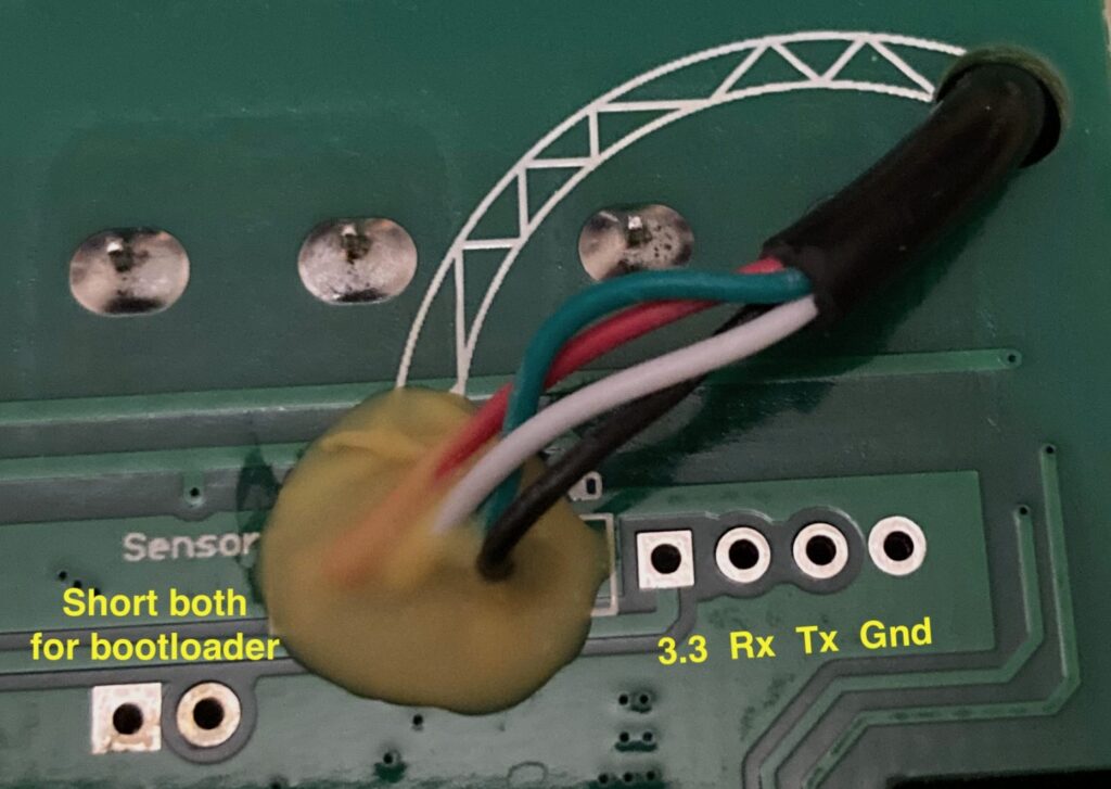
So I used the first instructions to locate the pins I needed to connect the smart controller to a FTDI adapter to back up the factory firmware and flash on ESPHome. First I disconnected the smart control box from the high-voltage supply (important!) and opened it up so I could get to the main PCB. There are six relevant pins: two you short to put the device into “bootloader” mode, and four corresponding to power, ground, transmit, and receive:
Image from the Tasmota guide showing pinouts for the serial connection.
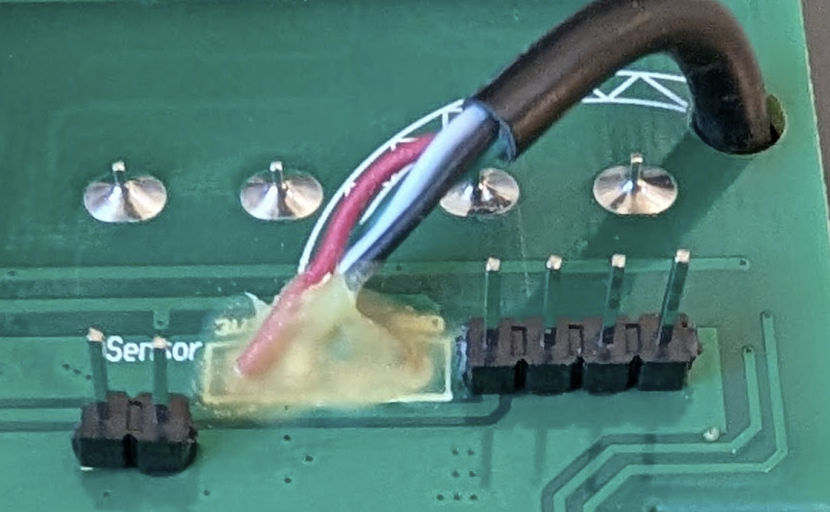
To make things easier, I soldered on headers for these:
I used this USB-to-serial adapter that came with a ribbon cable to connect the board to my Mac. No drivers or anything were required–it showed up as /dev/cu.usbserial-XXXXXXXX.
For safety, I pulled a backup of the factory firmware:
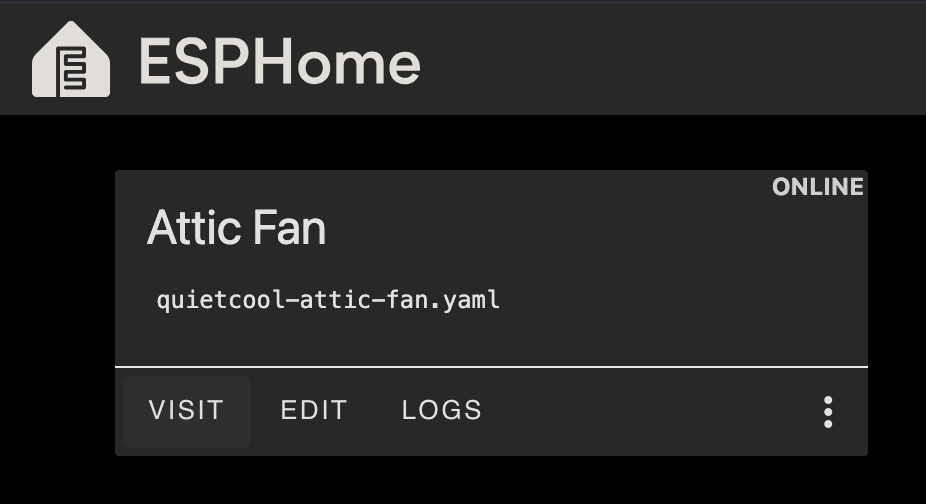
After this, the real magic of Home Assistant started to shine. Using the ESPHome Builder described in the setup guide and a bit of help from Claude, I created a YAML file that described the attic fan, including exposing a ‘fan’ entity. I was able to flash it directly from my browser using Webserial–how cool–even though the Home Assistant server was off in my utility closet.
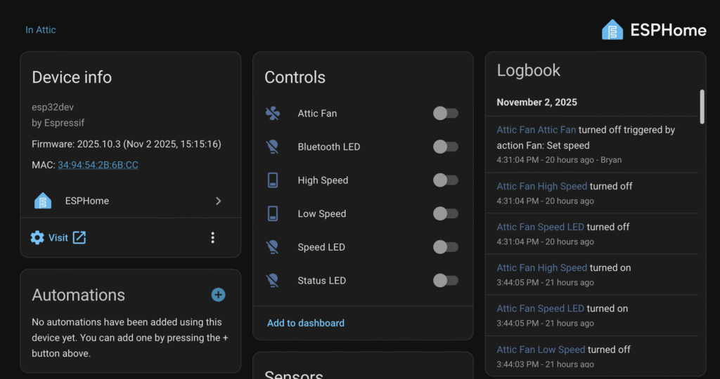
After the compilation of the firmware and flash (which took about 5 minutes), I pulled the bootloader jumper and power cycled the board, and it was automatically detected by Home Assistant:
Finally I reassembled the smart controller box and connected it back up to high-voltage supply and the inputs to the fan and it all worked like a charm. I’m definitely going to looking for more of these ESP-based devices to incorporate in the future…